In the era of trillion-parameter AI models, distributed GPU clusters have collided head-on with the physical limits of copper electrical interconnects. Routing 800 Gbps and 1.6 Tbps signals through copper DAC (Direct Attach Copper) cables and PCB traces incurs catastrophic electrical skin-effect attenuation, dielectric loss, and thermal dissipation. The undisputed future of high-speed scale-up interconnects is Silicon Photonics and Co-Packaged Optics (CPO), replacing copper traces with optical waveguides etched directly into silicon. At the center of this optical revolution sits the most compact, energy-efficient optical modulator ever engineered: the Silicon Micro-Ring Resonator (MRR).
With a physical footprint under 10 microns and the ability to modulate light at 64 Gbps using less than 10 femtojoules per bit (fJ/bit), micro-ring resonators enable ultra-dense Dense Wavelength Division Multiplexing (DWDM), routing 64 to 128 independent optical channels through a single microscopic fiber. But silicon micro-ring resonators suffer from a notorious, physics-mandated Achilles’ heel: extreme thermal drift. Silicon’s massive thermo-optic coefficient shifts the ring’s resonance wavelength by 0.1 nm per °C. In an AI server where GPU thermal spikes swing temperatures by 40°C in milliseconds, an unmanaged micro-ring detunes completely, crashing optical communication. Here is the deep engineering reality of micro-ring resonator physics, the thermal drift crisis, and how integrated micro-heaters and athermal claddings solve it.
1. Micro-Ring Resonator Physics: Whispering Gallery Modes and High Q-Factor
To appreciate why micro-ring resonators are so uniquely sensitive to temperature, one must first understand their optical operating mechanics. A silicon micro-ring resonator consists of a straight bus optical waveguide positioned in close proximity (separated by a coupling gap of 100 to 200 nanometers) to a circular closed-loop silicon waveguide with a radius typically between 3 and 10 microns.
When broadband laser light traverses the input bus waveguide, evanescent optical coupling transfers light across the narrow gap into the circular cavity. Light circulates continuously around the ring via total internal reflection, establishing a whispering gallery resonant mode.
Optical resonance occurs if and only if the optical round-trip phase accumulation is an exact integer multiple of 2π. This satisfies the fundamental resonant condition:
Where:
- m: The azimuthal mode order (a positive integer, typically m ≈ 40 to 120 in telecommunication wavelengths).
- λres: The resonant wavelength in vacuum (typically centered around 1310nm O-band or 1550nm C-band).
- R: The physical radius of the micro-ring waveguide.
- neff: The effective refractive index of the guided optical mode in the silicon waveguide core (typically neff ≈ 2.4 to 2.6 for silicon with SiO2 cladding).
At the resonant wavelength λres, light interfering inside the ring builds constructively. Destructive interference occurs in the through-port output of the bus waveguide, creating an exceptionally sharp, narrow transmission notch (a Lorentzian dip).
The sharpness of this resonance is quantified by the Quality Factor (Q-factor), defined as Q = λres / ΔλFWHM, where ΔλFWHM is the Full Width at Half Maximum of the resonance notch. High-speed optical modulators engineer Q-factors between 15,000 and 30,000. At Q = 20,000, the spectral passband ΔλFWHM is a razor-thin 0.075 nanometers (approx. 10 GHz optical bandwidth)!
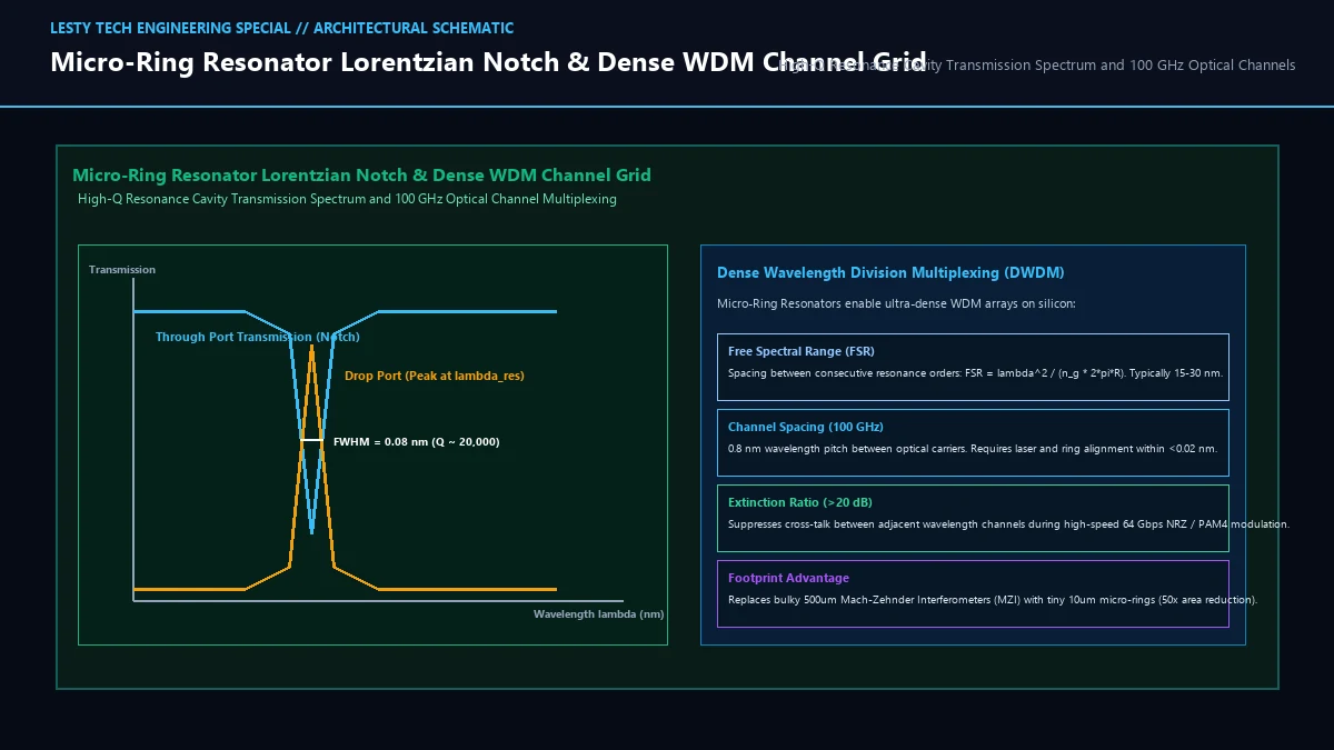
This exceptionally sharp spectral filtering enables Dense Wavelength Division Multiplexing (DWDM). By cascading 16, 32, or 64 micro-rings along a single bus waveguide, each tuned to a distinct resonant wavelength spaced at 100 GHz (0.8nm) or 50 GHz (0.4nm) intervals, an optical transceiver multiplexes dozens of multi-gigabit data streams across a single optical strand.
2. The Thermo-Optic Bottleneck: Silicon’s 0.1nm/°C Sensitivity
The very property that makes micro-ring resonators so compact and spectrally selective—their extreme optical confinement and high Q-factor—renders them acutely vulnerable to thermal variations.
Crystalline silicon possesses one of the highest thermo-optic coefficients (TOC, dn/dT) of any optical semiconductor:
Differentiating the resonant condition with respect to temperature reveals how the resonance wavelength drifts with ambient thermal changes:
Where ng is the group index of the waveguide (ng ≈ 4.0 to 4.2 in sub-micron silicon wires) and αthermal is the linear thermal expansion coefficient of silicon (α ≈ 2.6 × 10⁻⁶ K-1).
Plugging in real physical values reveals that thermal expansion of the physical ring radius R contributes less than 5% of the total shift. The overwhelming driver is the positive thermo-optic coefficient (dn/dT):
- The resonance wavelength red-shifts by approximately +0.08 nm to +0.11 nm per °C (+10 to +14 GHz per °C).
- Recall that a high-Q micro-ring has a resonance notch width (ΔλFWHM) of only 0.075 nm.
- This means a temperature change of a mere 0.8°C shifts the resonance completely out of alignment with the transmission laser!
- In an AI accelerator server, workload bursts cause local silicon junction temperatures to swing dynamically between 40°C at idle and 95°C under full GEMM load. A 55°C temperature swing causes the micro-ring resonance to drift by more than 5.5 nanometers—spanning across six adjacent DWDM channels and generating catastrophic optical cross-talk, bit-error rate (BER) collapse, and link failure.
3. Closed-Loop Thermal Stabilization: Integrated TiN Micro-Heaters
Because ambient temperature stability in an enterprise datacenter can never be guaranteed to within 0.1°C, every production micro-ring resonator co-packages an active closed-loop thermal tuning system.
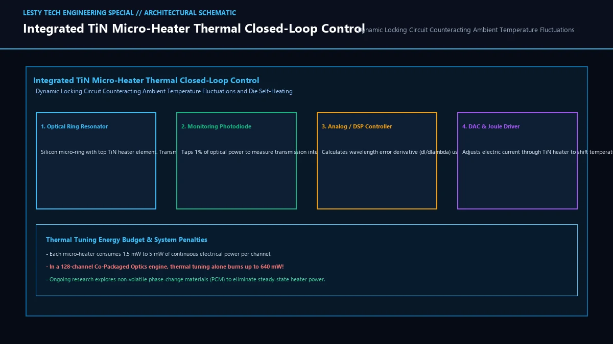
The standard industry solution is the integration of a microscopic Titanium Nitride (TiN) or Nickel-Chromium (NiCr) Joule heater fabricated directly above the optical ring:
- Heater Microfabrication: A thin metallic resistive ribbon (typically 100nm thick, 1 to 2 microns wide) is patterned in the upper backend-of-line (BEOL) dielectric layer, separated from the optical waveguide by 1.0 to 1.5 microns of SiO2 cladding to prevent metal absorption loss.
- Baseline Temperature Elevation: Because thermo-electric coolers (Peltier coolers) are too bulky and slow for individual micro-rings, heaters can only add thermal energy. Therefore, the micro-ring array is deliberately heated to a baseline temperature above the maximum anticipated die temperature (e.g., Tbaseline = 105°C).
- Feedback Error Detection: An integrated germanium tap photodiode samples 1% to 2% of the optical output power from the through-port. An analog front-end or digital signal processor (DSP) executes a dither lock-in detection algorithm, injecting a tiny 10 kHz sinusoidal oscillation into the heater drive current to calculate the error derivative (dI/dλ).
- Dynamic Current Compensation: As the host GPU heats up from 40°C to 80°C, the digital controller throttles electrical current through the TiN heater, keeping the net local temperature of the micro-ring locked precisely at 105°C within ±0.05°C.
4. Optical Crosstalk, Inter-Channel Beat Noise, and Finite Element Analysis
When scaling micro-ring resonator architectures to 64 or 128 channels in high-density Co-Packaged Optics, thermal drift introduces another severe physical threat: inter-channel optical crosstalk and heterodyne beat noise.
In a Dense Wavelength Division Multiplexing system operating on a 100 GHz (0.8nm) grid, adjacent optical carriers pass through neighboring micro-rings. If ring k drifts thermally by just 0.2 nm toward ring k+1, the tail of its Lorentzian passband begins to leak optical photons from the adjacent laser channel. This leakage mixes coherently at the photodetector surface, generating high-frequency heterodyne beat noise that severely degrades the Optical Signal-to-Noise Ratio (OSNR) and collapses the receiver’s eye diagram.
To quantify these thermal gradients, packaging foundries run rigorous 3D Finite Element Analysis (FEA) simulations. In a co-packaged multi-chiplet module, heat generated by adjacent 800-Watt GPU compute dies dissipates laterally through the organic or glass packaging substrate into the photonic integrated circuit (PIC). A 10°C thermal gradient across a 2-millimeter photonic die detunes individual rings at different rates! Silicon photonic architects must layout micro-rings in interleaved spatial patterns and incorporate thermal isolation trenches (air-filled micro-trenches etched into the silicon handle wafer) to isolate rings from host ASIC heat blooms.
5. The Thermal Power Paradox: When Tuning Burns More Watts Than Optics
While integrated micro-heaters successfully solve the thermal drift failure mode, they introduce a devastating architectural paradox: the thermal tuning energy penalty.
The primary motivation for adopting silicon photonics is ultra-low energy modulation: a micro-ring electro-optic modulator operates via carrier injection or depletion in a reverse-biased PN junction, consuming a tiny 5 to 15 femtojoules per bit (0.5 to 1.5 mW at 100 Gbps).
However, resistive Joule micro-heaters require substantial thermal tuning efficiency, typically 1.5 mW to 3.5 mW of electrical power per nanometer of wavelength tuning:
In a high-bandwidth Co-Packaged Optics switch or GPU inter-socket interface featuring 64 DWDM wavelength channels, thermal tuning heaters alone consume:
64 channels × 13.75 mW ≈ 880 milliwatts of pure parasitic heat!
In this scenario, thermal stabilization consumes nearly 10× more electrical power than the actual optical data modulation itself. If silicon photonics cannot solve this thermal power overhead, optical interconnects risk losing their efficiency advantage over advanced electrical SerDes.
6. Athermal Waveguides and Non-Volatile Optical Tuning
To eliminate continuous heater power dissipation, optical research institutions (MIT, IMEC, UCSB) are commercializing passive athermal architectures:
- Negative Thermo-Optic Cladding: While crystalline silicon has a positive thermo-optic coefficient (+1.86 × 10⁻⁴ K-1), certain optical polymers and dielectric oxides possess a strongly negative thermo-optic coefficient. Materials like Titanium Dioxide (TiO2, dn/dT ≈ -2.0 × 10⁻⁴ K-1) or specialized siloxane polymers deposited over a slotted silicon waveguide allow the optical mode to overlap with both materials simultaneously. As temperature rises, the negative shift of the cladding perfectly cancels the positive shift of the silicon core, achieving athermal performance (dλ/dT < 0.005 nm/°C) over an 80°C window with zero electrical heater power.
- Non-Volatile Phase-Change Materials (PCM): By depositing nanometer-thin layers of antimony triselenide (Sb2Se3) or GST over the ring, short optical or electrical pulses can switch the material between amorphous and crystalline states. This shifts the effective index permanently without requiring continuous hold current, slashing static tuning power to absolute zero.
7. Optical Modulator Architecture Comparison
The following engineering comparison benchmarks Micro-Ring Resonators against competing optical modulation technologies across footprint, energy, bandwidth, and thermal sensitivity:
| Modulator Metric | Silicon Micro-Ring (MRR) | Mach-Zehnder (MZI) | Electro-Absorption (EAM) |
|---|---|---|---|
| Device Silicon Footprint | Sub-10 μm diameter (< 100 μm2) | 500 μm to 2,000 μm length (> 25,000 μm2) | 50 μm to 150 μm length |
| Modulation Energy (Active) | 5 to 20 fJ / bit (Ultra-low) | 500 to 2,000 fJ / bit (High capacitance) | 50 to 150 fJ / bit |
| Thermal Wavelength Sensitivity | Extreme (~0.1 nm / °C) | Negligible (Broadband interferometer) | Moderate (~0.4 nm / °C bandgap) |
| Thermal Tuning Overhead | 2 to 15 mW per channel (Required) | 0 mW (Athermal by design) | 0 to 2 mW per channel |
| DWDM Multiplexing Density | Native (64 to 128 channels / fiber) | Requires discrete optical AWG mux | Moderate (8 to 16 channels) |
| Primary Deployment Sector | Co-Packaged Optics & AI Scale-Up | Pluggable Transceivers (QSFP-DD, OSFP) | Telecom Long-Haul & Datacenter DCI |
Silicon Photonics Micro-Ring Resonators & Thermal Drift Engineering
Combating 0.1nm/°C Thermo-Optic Shifts, High-Q Cavities, and DWDM Co-Packaged Optics (Complete architectural audit with telemetry tables and schematic breakdowns).
Silicon_Photonics_Micro_Ring_Resonators_and_Thermal_Drift_Dossier.pdfFormat: PDF / KaTeX Telemetry