Over the past five years, the consumer power electronics market underwent a silent, massive revolution: the total conquest of Gallium Nitride (GaN). The days of hauling heavy, brick-like black plastic power adapters to charge laptops, tablets, and smartphones have virtually vanished. In their place, sleek, pocket-sized chargers promising 100W, 140W, and even 240W of output power dominate Amazon best-seller lists and airport carry-on bags. Packed with two, three, or four USB-C ports, these modern engineering marvels promise to charge your power-hungry 16-inch MacBook Pro, your iPad, and your smartphone simultaneously from a single compact wall plug.
Yet behind the glossy marketing renders and promises of universal power lies a dirty technical reality that charger manufacturers rarely explain on the box: the dynamic multi-port power cliff, handshake interruption freezes, and punishing thermal density. When a manufacturer advertises a “140W 3-Port GaN Charger,” that maximum wattage is only available when a single port is active. The second you plug in a tiny 5-watt smartwatch or a pair of wireless earbuds into Port 2, the charger’s microcontroller forcefully resets the USB Power Delivery (USB PD) communication bus, instantaneously cutting off power and downgrading your laptop’s primary port from 140W down to 65W or 45W! Meanwhile, pushing 140W to 240W through a plastic enclosure no larger than a deck of cards pushes internal component temperatures past 100°C, triggering aggressive thermal throttling that cuts charging speeds in half after twenty minutes. Here is the unvarnished engineering reality of GaN power electronics, how the USB PD 3.1 Extended Power Range (EPR 240W) standard operates at 48 volts, and what spec sheets conceal from consumers.
1. Solid-State Physics: Why GaN Replaced Silicon Power MOSFETs
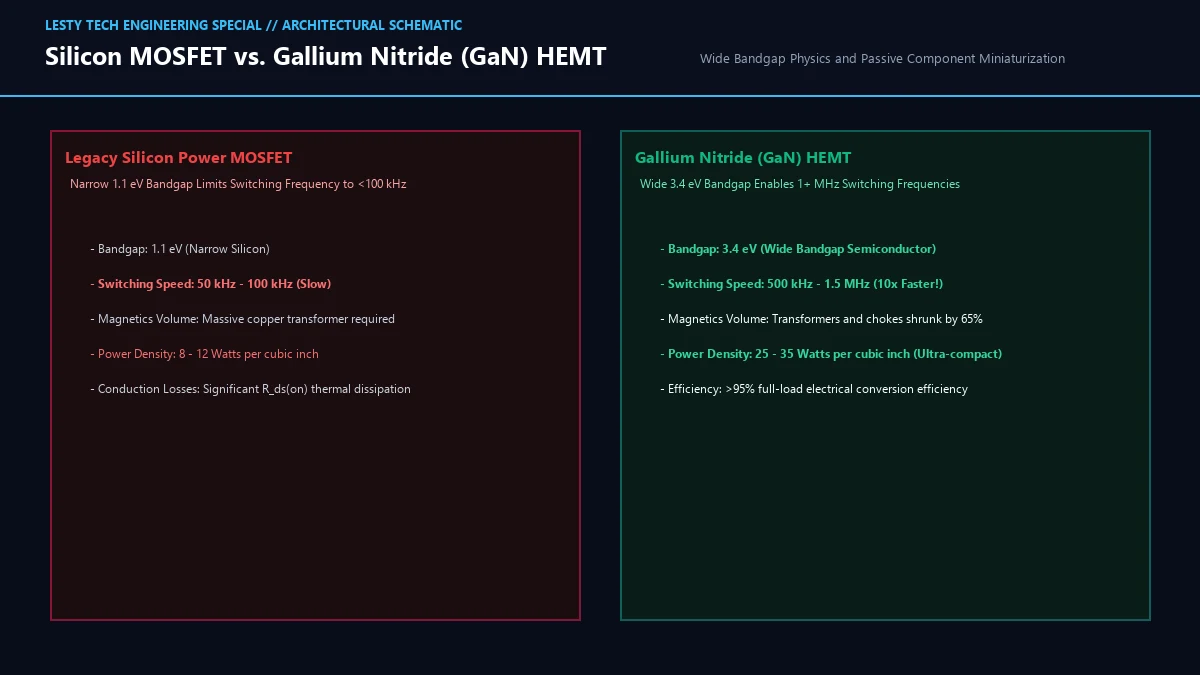
To understand why GaN chargers are so small, one must look at the solid-state physics of wide-bandgap semiconductors. For sixty years, power supplies (switched-mode power supplies, or SMPS) converted alternating current (110V/220V AC) from wall outlets into direct current (DC) using silicon-based power MOSFETs (Metal-Oxide-Semiconductor Field-Effect Transistors).
In a switched-mode power supply, electricity is converted by rapidly chopping incoming voltage on and off hundreds of thousands of times per second, directing pulses through magnetic transformers and smoothing capacitors. The size of the magnetic components (the copper transformer core and inductors) is mathematically inversely proportional to the switching frequency:
The higher the switching frequency, the smaller the copper transformer coils and filtering capacitors can be.
However, silicon is fundamentally limited by its material bandgap. Silicon has a narrow energy bandgap of 1.1 electron-volts (eV) and a critical breakdown electric field of roughly 0.3 MV/cm. If an engineer attempts to switch a high-voltage silicon MOSFET faster than 80 kHz to 100 kHz, the transistor’s internal parasitic capacitance (gate charge Qg and output capacitance Coss) causes switching losses to skyrocket:
At high frequencies, silicon transistors overheat and self-destruct. Consequently, legacy laptop power bricks were forced to operate at a sluggish 60 to 100 kHz, necessitating massive, heavy iron-ferrite transformer cores and bulky 400V electrolytic capacitors that made chargers the size and weight of a construction brick.
Enter Gallium Nitride (GaN). GaN is a Wide-Bandgap (WBG) compound semiconductor with an atomic bandgap of 3.4 electron-volts (eV)three times wider than silicon. In a GaN High Electron Mobility Transistor (HEMT), the spontaneous polarization of the gallium-nitrogen crystal lattice creates a microscopic layer of free electrons known as a Two-Dimensional Electron Gas (2DEG).
The 2DEG layer grants GaN extraordinary physical advantages:
- 10x Higher Breakdown Field: GaN withstands electrical fields up to 3.3 MV/cm, allowing the transistor to be built ten times thinner than silicon for an identical 650V rating.
- Ultra-Low Gate Charge and Capacitance: GaN HEMTs switch from fully conducting to completely non-conducting in less than 2 to 5 nanoseconds roughly 100 times faster than silicon.
- Megahertz Switching Frequencies: GaN power supplies operate comfortably at switching frequencies ranging from 300 kHz to 1.5 MHz (Zero Voltage Switching, ZVS).
By scaling switching frequency up by 10×, the physical size of magnetic transformers, inductors, and filtering capacitors shrinks by more than 60%. This is the physical secret that allowed power densities to surge from 810 Watts per cubic inch in legacy silicon chargers up to 25 to 35 Watts per cubic inch in modern GaN chargers.
2. The USB Power Delivery 3.1 EPR Revolution: 240W at 48 Volts
For years, USB Type-C charging was capped under the USB PD 3.0 Standard Power Range (SPR) specification at 100 Watts (20 Volts at 5 Amps). While 100W was plenty for smartphones, tablets, and 13-inch ultrabooks, it fell far short of satisfying high-performance 16-inch laptops, creative mobile workstations, and gaming notebooks, which demand 140W to 240W under full CPU/GPU loads.
Why couldn’t USB-IF simply increase the electrical current past 5 Amps?
The answer is Joule heating: electrical power loss in a cable conductor scales quadratically with current:
Pushing 10 or 12 Amps through the microscopic contact pins of a USB-C connector would generate catastrophic resistive heat, melting the connector housing and sparking fire hazards. Current had to remain locked at a strict maximum ceiling of 5 Amps.
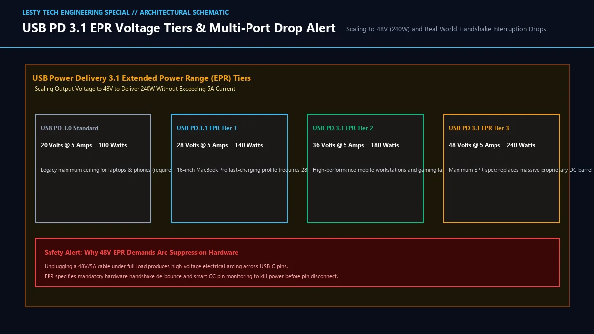
To scale power to 240 Watts, the USB Implementers Forum (USB-IF) published USB Power Delivery 3.1 Extended Power Range (EPR). EPR breaks the 20V ceiling by introducing three high-voltage operational tiers:
- Tier 1: 28 Volts @ 5 Amps = 140 Watts: First commercialized by Apple in the 16-inch MacBook Pro (M1/M2/M3 Max). Allows laptops to fast-charge from 0% to 50% in 30 minutes.
- Tier 2: 36 Volts @ 5 Amps = 180 Watts: Targeted at high-end creative laptops with discrete GPUs.
- Tier 3: 48 Volts @ 5 Amps = 240 Watts: The maximum standardized ceiling of USB Power Delivery, capable of replacing proprietary DC barrel-jack power bricks on flagship gaming laptops.
However, operating at 48 Volts introduces severe electrical engineering challenges:
- Capacitor Voltage Headroom: In electrical design, smoothing capacitors must have a rated breakdown voltage at least 20% to 30% higher than the peak line voltage. To support 48V EPR, charger manufacturers must fit 50V to 63V solid polymer capacitors inside miniature enclosures. Higher-voltage capacitors are physically larger and significantly more expensive.
- Electrical Arcing Suppression: At 48 Volts DC and 5 Amps, hot-unplugging a USB-C cable creates a high-voltage electrical plasma arc across the connector pins. Over time, plasma arcing pits and oxidizes the gold-plated pins, causing premature connector failure. To prevent this, USB PD 3.1 mandates an active arc-suppression handshake protocol: when the CC (Configuration Channel) pin detects physical disconnection, the charger cuts high-voltage output within 15 microseconds before the primary power pins physically disengage.
- Authenticated E-Marker Cables: Standard USB-C cables are physically barred by hardware chips from negotiating EPR voltages. To access 140W to 240W, users must utilize certified USB PD 3.1 EPR cables containing electronic marker (E-Marker) microcontrollers that verify the cable’s 50V insulation rating with both the charger and the host device.
3. The Dirty Secret: Dynamic Multi-Port Power Drops and Handshake Freezes
The single greatest source of consumer frustration with multi-port GaN chargers is the phenomenon of dynamic power allocation drops and handshake renegotiation freezes.
Consider this real-world scenario: you purchase a top-tier “140W 3-Port GaN Charger.” You plug your high-end laptop into USB-C Port 1. The charger negotiates a 140W (28V/5A) USB PD 3.1 profile. Your laptop’s CPU and GPU boost to maximum turbo clocks.
Twenty minutes later, you plug a pair of wireless earbuds (consuming just 2.5 Watts) into USB-C Port 2.
Instantly, three infuriating things occur simultaneously:
- The Blackout Disconnect Freeze: The screen on your laptop blinks, connected external monitors reset, and the battery charging icon vanishes for 2 to 3 seconds.
- The Violent Power Drop: When power returns, Port 1 does NOT resume at 140W. It is instantaneously downgraded to 65W (20V/3.25A)a staggering 54% loss in charging throughput!
- Performance Throttling & Battery Drain: Because your laptop was drawing 110W under heavy computational load, dropping input power to 65W forces the laptop into severe battery-supplement mode: the CPU throttles its clock speeds by 30%, and the laptop battery actively drains while plugged into the wall!
Why does this happen?
To minimize production costs, budget and mid-tier multi-port GaN chargers do NOT contain independent power transformer stages for each port. Instead, they utilize a single monolithic primary GaN transformer paired with a shared DC-DC buck converter array managed by a single central microcontroller.
When a second device is plugged in, the microcontroller cannot dynamically shift a few milliwatts to Port 2 while leaving Port 1 running. The USB Power Delivery specification requires a synchronous hardware handshake. The microcontroller must forcefully reset the VBUS power line to 0 Volts across ALL ports simultaneously, interrogate the e-marker chips of all connected devices, calculate a pre-programmed power-splitting table stored in firmware, and re-negotiate new power contracts with all devices.
4. The Thermal Density Reality: Inside the 85°C Plastic Shell
The second hidden trade-off of compact GaN chargers is thermal dissipation. While GaN is remarkably efficient (>93% to 95% full-load electrical conversion efficiency), thermodynamics is unforgiving.
When a compact GaN charger outputs 140 Watts at 94% efficiency:
In a full-sized desktop PC power supply with a 120mm cooling fan, dissipating 8.4 watts of heat is trivial. But in an ultra-compact GaN charger measuring just 65mm × 65mm × 30mm (volume ≈ 7.6 cubic inches) with zero moving parts, zero ventilation holes, and a sealed plastic outer enclosure, 8.4 watts of heat is a massive thermal load.
In budget GaN chargers lacking active thermal potting, heat becomes trapped inside internal air pockets. Internal temperatures on the primary GaN HEMT transistors and transformer windings rapidly spike to 110°C to 125°C, while the outer plastic casing reaches 80°C to 88°C (176°F to 190°F)hot enough to cause superficial burns and warp plastic enclosures.
To prevent fire hazards and satisfy international safety regulations (IEC 62368-1), the charger’s internal thermal sensor triggers Over-Temperature Protection (OTP) throttling. After 15 to 25 minutes of continuous full-power charging, the charger silently cuts output wattage by 30% to 50% until internal temperatures cool, doubling total battery recharge times.
Premium GaN charger engineering (exemplified by high-end units from Anker, UGREEN, and Satechi) combats this through advanced thermal packaging:
- Full Thermal Potting Compound: The entire internal cavity is injected with high-density thermally conductive silicone resin, completely eliminating air gaps and conducting heat uniformly from hot transistors out to the entire surface of the casing.
- Internal Copper Vapor Chambers: Thin, planar copper heat spreaders wrap around the transformer and power stages, spreading thermal flux across all six faces of the outer shell.
5. GaN Charger Technology & Architectural Comparison Table
Review the engineering, electrical, and thermal differences across modern charger generations:
| Charger Category | Legacy Silicon (65W) | Budget Multi-Port GaN (100W) | Premium Dual-GaN (140W EPR) | Flagship USB PD 3.1 (240W EPR) |
|---|---|---|---|---|
| Power Density | 812 W/in3 (Bulky Brick) | 1822 W/in3 | 2530 W/in3 | 3238 W/in3 (Ultra-Dense) |
| Max Peak Voltage | 20V (Standard SPR) | 20V (Standard SPR) | 28V (USB PD 3.1 EPR) | 48V (USB PD 3.1 EPR) |
| Switching Frequency | 65100 kHz (Slow) | 250450 kHz | 500 kHz1.0 MHz (ZVS) | 800 kHz1.5 MHz (Zero Voltage) |
| Multi-Port Handshake Drop | N/A (Single Port) | Severe (-55% Wattage Drop) | Moderate (Re-allocates to 100W) | Dual-Stage Independent Rails |
| Thermal Management | Air Convection | Basic Heat Spreaders (Hot Shell) | Full Silicone Potting Resin | Vapor Chamber + Full Potting |
| Full-Load Surface Temp | 4555°C (Cool) | 7888°C (Throttles) | 6272°C (Sustained) | 6575°C (Sustained Full-Load) |
6. Practical Consumer Buying Guide & Optimization Checklist
When shopping for a high-wattage GaN charger in 2026, use these field-tested engineering rules to avoid buyer’s remorse:
- Scrutinize the Power Distribution Table: Never buy a charger based solely on the headline wattage printed on the box. Flip the packaging over and examine the microscopic multi-port distribution matrix. If a “100W 3-Port” charger drops Port 1 to 45W when Port 2 is active, it cannot power a 15-inch or 16-inch laptop under load. Look for models that maintain at least 65W to 100W on Port 1 during multi-device charging.
- Verify USB PD 3.1 EPR Certification: If you own a 16-inch MacBook Pro or a modern high-power gaming laptop, ensure the charger explicitly specifies USB PD 3.1 Extended Power Range (EPR) with 28V/5A or 48V/5A support. A standard 100W PD 3.0 charger cannot fast-charge these laptops at full 140W speeds.
- Demand Verified E-Marker Cables: Your 240W GaN charger is completely useless if paired with a generic $5 USB-C cable. Standard USB-C cables are electronically capped at 60W (20V/3A) or 100W (20V/5A). To charge at 140W or 240W, you must pair the charger with a certified 240W USB-IF E-Marker cable rated for 48V/5A operation.
- Check for Thermal Potting Compound: Prefer chargers that explicitly advertise full thermal potting resin (such as Anker GaNPrime or UGREEN Nexode Pro). Full potting prevents localized hot spots, eliminates internal capacitor whining (coil whine), and prevents premature thermal throttling.
Gallium Nitride (GaN) Power Architecture & USB PD 3.1 EPR Guide
Hardware Analysis: 240W Extended Power Range, Dynamic Multi-Port Power Drops, and Thermal Limits (Complete architectural audit with telemetry tables and schematic breakdowns).
GaN_Fast_Chargers_and_USB_PD31_EPR_Thermal_Guide.pdfFormat: PDF / KaTeX Telemetry
Frequently Asked Questions (FAQ)
1. Why do GaN chargers briefly disconnect all devices when a new device is plugged in?
This occurs because the charger must re-negotiate power contracts via the USB Power Delivery protocol. Most multi-port chargers share a central power rail. When a new device is attached to Port 2, the charger’s microcontroller temporarily resets the VBUS line across all ports to 0 Volts, reads the power requirements of all connected devices, and reconfigures internal DC-DC converter splitters according to its firmware power table before restoring voltage.
2. Can a 240W USB-C GaN charger damage a smartphone that only accepts 20W?
No. USB Power Delivery operates on an active digital negotiation protocol. A USB-C charger starts at a safe baseline of 5 Volts. The charger and phone communicate digitally over the Configuration Channel (CC) wire. The charger presents its supported voltage/current profiles, and the smartphone explicitly commands the charger to supply only what its internal battery management system (BMS) can safely handle (e.g., 9V at 2.22A = 20W). Power is pulled by the device, never pushed by the charger.
3. Do GaN chargers consume high “vampire” standby power when left plugged in without devices?
No. In fact, modern GaN chargers consume significantly less standby power than legacy silicon chargers. Under international Energy Star and EU Level VI efficiency mandates, modern GaN controllers feature ultra-low-power burst-mode and sleep-mode circuits that drop standby power consumption beneath 0.075 to 0.1 Watts. Leaving a modern GaN charger plugged into the wall 24/7 costs less than 15 to 20 cents per year in idle electricity.