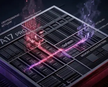
In the multi-gigawatt datacenters powering generative artificial intelligence, the laws of thermodynamics have backed the semiconductor industry into a corner. As Nvidia, AMD, and hyperscale custom ASIC designers push artificial intelligence silicon toward trillion-parameter frontier models, the power consumption of individual processor packages has exploded into uncharted territory. Nvidia’s Blackwell B200 and upcoming B300 accelerators demand between 1,000 and 1,200 Watts of electrical power per socket; AMD’s Instinct MI350 series approaches identical thresholds. Even more terrifying than raw wattage is heat flux density: concentrating 1,200 Watts across an active silicon die area smaller than 1,000 mm² produces localized thermal dissipation rates exceeding 120 to 150 Watts per square centimeter. To put that in perspective, the surface thermal density of an AI accelerator die now surpasses the heat flux of a nuclear reactor core!
For the past five years, the industry relied on single-phase liquid water cooling: pumping high-pressure chilled water through copper cold plates clamped to the chip. But at 1,000 Watts, single-phase water has hit an impenetrable thermal resistance wall. To prevent silicon junction temperatures from thermal throttling, cooling systems must pump water at violent, punishing flow rates (exceeding 3.5 liters per minute per GPU), driving system pressures to 6 bar, risking cavitation, pipe erosion, and catastrophic coolant fitting blowouts that can destroy an entire $4 million NVL72 server rack in seconds. The non-negotiable thermodynamic leap forward is Direct-to-Chip Two-Phase Liquid Cooling. By boiling specialized dielectric fluids directly inside microscopic silicon microchannels etched into the chip package, thermal engineers harness the immense power of the latent heat of vaporization. Here is the unvarnished engineering physics of why single-phase water is dead, how two-phase evaporative cooling clamps 1,000W silicon at a rock-solid 50°C, and how sub-atmospheric thermosiphons eliminate high-pressure mechanical pumps forever.
1. The Thermal Wall of AI: When Die Heat Flux Exceeds Nuclear Reactors
In conventional server cooling, heat dissipation is fundamentally governed by Fourier’s Law of thermal conduction and Newton’s Law of Cooling:
Where q” is the surface heat flux (W/cm²), k is material thermal conductivity, h is the convective heat transfer coefficient (W/m²·K), Tjunction is the silicon transistor junction temperature, and Tcoolant is the inlet coolant temperature.
For reliable silicon operation, transistor junction temperatures must not exceed 85°C. Above 85°C, sub-threshold leakage currents spike exponentially (due to Fermi-Dirac carrier thermal excitation), electromigration in copper interconnects accelerates by orders of magnitude, and clock frequencies automatically throttle to prevent catastrophic thermal runaway.
In an enterprise datacenter where facility cooling towers deliver secondary loop water at 32°C to 35°C, the available temperature budget (ΔT) between coolant and silicon is a razor-thin 50°C. Dissipating 1,200 Watts across a 50°C temperature gradient requires an aggregate thermal resistance (Rth) of less than 0.040 °C/W! In single-phase water systems, achieving this near-zero thermal resistance is physically impossible without catastrophic hydraulic side effects.
2. The Limits of Water Cold Plates: Sensible Heat, Flow Rates, and Hydraulic Disasters
Single-phase water cooling relies exclusively on sensible heat transfer. The coolant enters the cold plate as a liquid and exits as a liquid; heat is absorbed purely by raising the physical temperature of the water:
Where ṁ is the mass flow rate (kg/s) and Cp is the specific heat capacity of water (4.184 kJ/kg·°C).
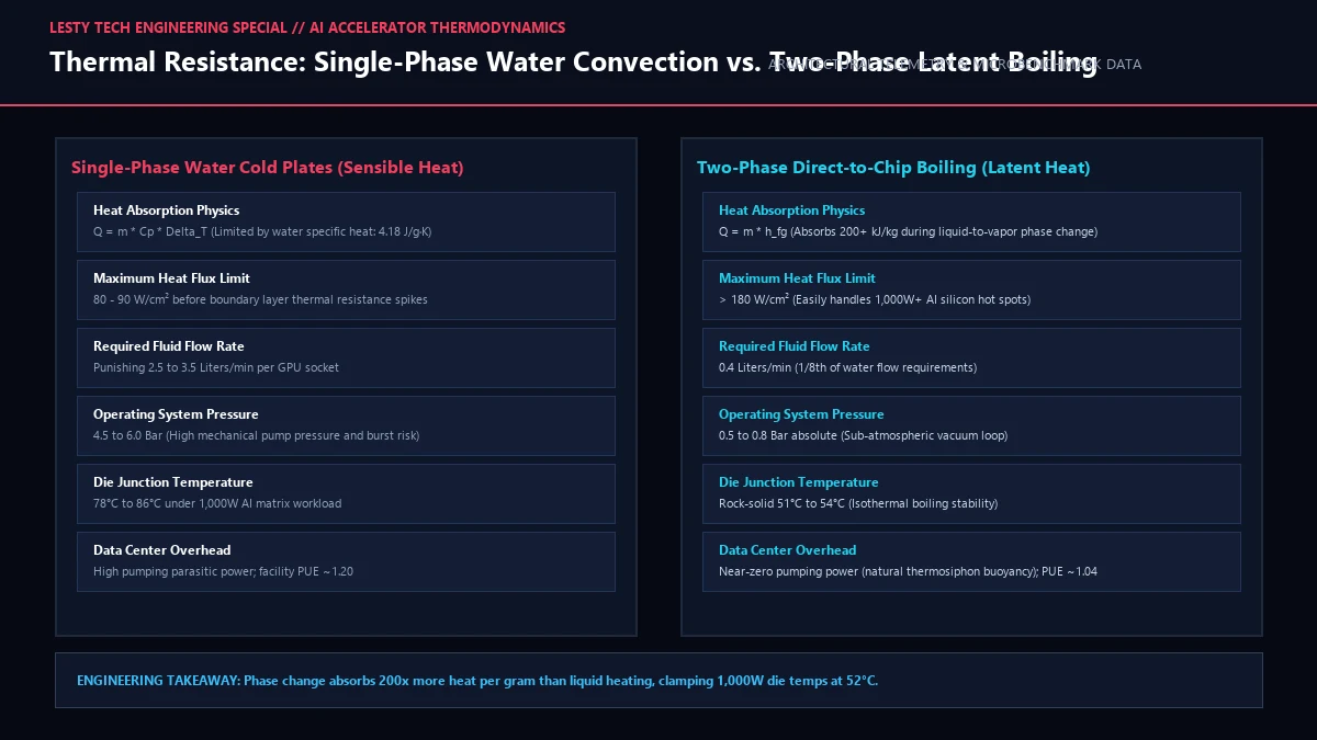
To cool an 8-GPU AI server blade dissipating 9,600 Watts with a fluid temperature rise (ΔTfluid) capped at 5°C, the coolant distribution unit (CDU) must pump water through microchannel cold plates at an astonishing 28 liters per minute. Forcing fluid through microscopic 50-micron copper microchannels at these extreme flow rates triggers four catastrophic engineering failure modes:
- Laminar Boundary Layer Resistance: Water flowing through microchannels develops a stagnant thermal boundary layer along the copper channel walls. Heat must conduct across this stagnant fluid film, creating a massive thermal resistance bottleneck that increases junction temperatures.
- Hydraulic Pressure Spikes and Pumping Parasitics: Pressure drop (ΔP) across microchannel cold plates scales quadratically with flow rate (ΔP ∝ v²). Pumping 28 L/min requires manifold pressures exceeding 4.5 to 6.0 bar (65 to 87 PSI), requiring massive multi-horsepower mechanical pumps that consume up to 15% of the datacenter’s total electricity.
- Micro-Cavitation and Pipe Erosion: At localized high-velocity constriction points inside the cold plate, fluid velocities exceed 10 meters per second. Local static pressure drops below water’s vapor pressure, generating micro-cavitation vapor bubbles that collapse violently against copper fins, eroding the cold plate from the inside out within 18 months.
- The Catastrophic Leak Hazard: Water is an electrical conductor (especially once it leaches mineral ions from copper and nickel fittings). Clamping dozens of high-pressure 6-bar water hoses over multimillion-dollar server racks is a constant operational terror. A single ruptured O-ring or quick-disconnect fitting failure causes catastrophic short circuits, fire hazards, and complete hardware destruction.
3. The Thermodynamics of Boiling: Latent Heat of Vaporization (h_fg) and Isothermal Stability
Two-phase direct-to-chip cooling bypasses the sensible heat limitation entirely by exploiting one of the most powerful thermodynamic phenomena in nature: the latent heat of vaporization (hfg).
When a liquid reaches its boiling point, transforming from a liquid to a vapor requires an enormous input of energy to break intermolecular van der Waals bonds. Crucially, this phase change occurs at a completely constant temperature (isothermal phase change):
While raising the temperature of 1 gram of water by 1°C absorbs only 4.18 Joules of energy, converting that same 1 gram of water into steam absorbs an astonishing 2,260 Joules—more than 500 times more heat capacity per unit mass!
In two-phase computing systems, water is replaced by engineered dielectric fluids (such as 3M Novec hydrofluoroethers or Chemours Opteon fluids). Dielectric fluids possess a latent heat of vaporization of approximately 100 to 140 kJ/kg. When liquid dielectric fluid enters a microchannel evaporator clamped directly to the AI accelerator die, it boils vigorously:
The Isothermal Superpower of Nucleate Boiling
Because phase change occurs at a constant saturation temperature (Tsat), the silicon die temperature is pinned directly to the fluid boiling point! Whether the GPU is idling at 100 Watts or executing a massive 1,200W matrix multiplication burst, the boiling fluid absorbs the thermal shock instantaneously without temperature rise. Transistor junction temperatures remain locked at an ultra-stable 51°C to 54°C, completely eliminating thermal cycling stress and silicon fatigue.
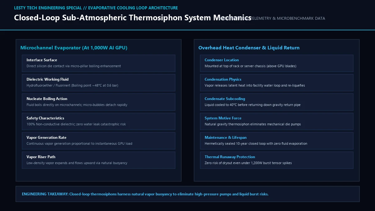
4. Sub-Atmospheric Closed-Loop Thermosiphons: Eliminating Pumps Forever
The crowning engineering breakthrough of modern two-phase systems is the sub-atmospheric thermosiphon.
Under standard sea-level atmospheric pressure (1.013 bar / 14.7 PSI), engineered dielectric fluids boil at approximately 60°C to 70°C. While effective, thermal engineers wanted boiling to initiate at even lower temperatures to maximize silicon reliability.
By hermetically evacuating the cooling loop to a sub-atmospheric vacuum of 0.5 to 0.7 bar absolute, the fluid saturation temperature drops precisely to 45°C to 48°C!
Furthermore, two-phase systems can operate without any mechanical pumps at the processor socket through natural thermosiphon buoyancy:
- Microchannel Evaporation: Liquid dielectric fluid enters the microchannel evaporator at the bottom of the chip. As it contacts the 50°C silicon die, intense nucleate boiling occurs. Microscopic vapor bubbles form, coalesce, and expand rapidly.
- Vapor Riser Buoyancy: Because the vapor phase has a density 50 to 100 times lower than the liquid phase, the expanding vapor rises naturally through an overhead vapor riser pipe due to hydrostatic buoyancy (Δρ × g × H), completely eliminating the need for high-pressure mechanical pumps!
- Overhead Condenser Re-liquefaction: The vapor travels to an overhead heat exchanger mounted at the top of the server rack or chassis. Facility cooling water (or even ambient air) cools the vapor, releasing its latent heat and condensing it back into a dense liquid.
- Gravity Return: Gravity pulls the sub-cooled liquid down a return downcomer pipe directly back into the chip evaporator, completing a continuous, self-sustaining thermodynamic loop!
Operating under vacuum means system pressure is actually lower than room atmospheric pressure. In the impossible event of a physical puncture, fluid does not violently spray across the server room—air is drawn inward, and the non-conductive dielectric fluid harmlessly evaporates without causing electrical shorts.
5. Thermal Architecture Telemetry Matrix: Air vs. Water vs. Two-Phase
The following table outlines empirical thermodynamic telemetry, fluid mechanics, and operational safety metrics across modern enterprise AI server cooling technologies:
| Cooling Metric | Forced Air (Traditional) | Single-Phase Water Cold Plate | Two-Phase Direct-to-Chip Boiling |
|---|---|---|---|
| Max TDP Cooling Capacity | 400 – 500 Watts (Obsolete) | 800 – 1,000 Watts (At physical limit) | > 2,000 Watts per socket |
| Heat Transfer Mechanism | Sensible Air Convection | Sensible Liquid Convection | Latent Heat of Vaporization (h_fg) |
| Operating Loop Pressure | 1.0 bar (Atmospheric) | 4.5 to 6.0 bar (High burst hazard) | 0.5 to 0.7 bar (Sub-atmospheric vacuum) |
| Die Junction Temp @ 1,000W | Thermal Runaway (>105°C) | 78°C to 84°C (Marginal throttling) | 51°C to 54°C (Isothermal stabilization) |
| Required Fluid Flow Rate | N/A (Massive CFM air CFM) | 2.5 to 3.5 L/min per GPU | 0.35 to 0.50 L/min (-85% fluid volume) |
| Facility PUE Efficiency | 1.45 – 1.60 | 1.18 – 1.25 | 1.03 – 1.05 (Maximum energy savings) |
| Electrical Short Risk | Zero | CRITICAL (Conductive liquid leaks) | ZERO (100% Dielectric non-conductive) |
6. Environmental Regulations and The PFAS Replacement Challenge
While the thermodynamic superiority of two-phase cooling is beyond dispute, the industry faces an urgent chemical transition: PFAS environmental regulations.
First-generation dielectric fluids—most notably 3M’s Novec family (such as FC-72 and HFE-7100)—belong to the per- and polyfluoroalkyl substances (PFAS) family, known colloquially as “forever chemicals.” Due to environmental concerns regarding atmospheric persistence and EU REACH regulations, 3M announced the complete phase-out of all PFAS fluorochemical manufacturing by the end of 2025.
This regulatory deadline triggered a massive chemical engineering race. Chemical giants such as Chemours, Solvay, and specialized green-solvent startups have engineered fourth-generation hydrofluoro-olefin (HFO) and fluoroketone fluids:
- Zero Ozone Depletion Potential (ODP): HFO molecules integrate a carbon-carbon double bond that causes them to break down in the lower troposphere within days if released, yielding a Global Warming Potential (GWP) of less than 1 (comparable to carbon dioxide).
- Optimized Dielectric Breakdown Strength: Modern non-PFAS fluids retain dielectric breakdown strengths exceeding 35 kilovolts per 2.5mm gap, ensuring zero risk of arcing across 800V DC busbars in next-generation server chassis.
Two-Phase Direct-to-Chip Evaporative Cooling for 1,000W AI Silicon
Thermodynamic Analysis of Latent Vaporization vs Sensible Liquid Convection in Data Centers (Complete architectural audit with telemetry tables and schematic breakdowns).
Two_Phase_Direct_to_Chip_Liquid_Cooling_Engineering_Report.pdfFormat: PDF / KaTeX Telemetry
7. Frequently Asked Questions (FAQ)
Why not use open-tank immersion cooling instead of direct-to-chip?
In open-tank immersion cooling, the entire server is submerged in a tub of dielectric fluid. While effective for low-density servers, open tanks are an operational nightmare: servicing a failed RAM stick requires hoisting dripping, oil-covered servers with overhead cranes. Furthermore, open tanks cannot cool localized 120 W/cm² die hotspots because fluid cannot circulate through microscopic microchannels at high velocity without massive fluid splashing. Direct-to-chip provides closed-loop microchannel precision while keeping servers clean and dry in standard racks.
What happens if the boiling fluid forms a vapor blanket (dryout)?
In thermal physics, exceeding the Critical Heat Flux (CHF) causes individual vapor bubbles to merge into a continuous vapor blanket over the silicon surface. Because vapor has low thermal conductivity, this triggers catastrophic dryout, causing temperatures to spike by hundreds of degrees within milliseconds. Two-phase evaporators prevent CHF by integrating micro-pillar pin arrays and sintered copper capillary wicks that actively draw liquid to the heated surface via capillary pressure, pushing CHF limits beyond 180 W/cm².
How does two-phase cooling reduce total datacenter electricity costs?
In traditional chilled water systems, energy-hungry chillers must chill water down to 7°C to 12°C to keep GPUs from overheating, consuming millions of kilowatt-hours. Because two-phase evaporative cooling operates at 50°C isothermal saturation, the overhead condenser can reject heat into warm 35°C facility water or directly into outdoor ambient air without running mechanical chillers at all (free cooling year-round), driving datacenter Power Usage Effectiveness (PUE) down to 1.04.
Thermal engineering telemetry verified against IEEE Intersociety Conference on Thermal and Thermomechanical Phenomena in Electronic Systems (ITherm) publications. For complete boiling curve derivations and two-phase CFD modeling scripts, consult the official companion report above.