In the engineering of modern high-performance desktop PCs, workstation computing rigs, and AI accelerator workstations, no hardware transition has generated more consumer anxiety and mechanical controversy than the introduction of high-power 12V GPU power connectors. When the PCI-SIG and Intel ratified the ATX 3.0 specification introducing the 16-pin 12VHPWR connector capable of delivering up to 600 Watts over a single cable to flagship GPUs (such as the NVIDIA GeForce RTX 4090), reports of melted terminal housings, burned pins, and catastrophic socket failure proliferated across tech communities. In response, the PCI-SIG and Intel issued an urgent architectural overhaul: the ATX 3.1 standard and the 12V-2×6 connector specification. In this comprehensive, hardware-grounded buyer and engineering guide, we dissect the electrical physics governing atx 3.1 vs atx 3.0 power supplies, examining the minute terminal recess modifications, 200% transient power excursion tolerances, hold-up time adaptations, and verified safety checklists required to protect next-generation PCIe Gen 5 and Gen 6 graphics hardware.
1. The Electrical Physics of the 12VHPWR Connector Failure Mechanism
In this technical engineering analysis of atx 3.1 power supplies, To understand why the original ATX 3.0 12VHPWR connector suffered from high-profile thermal failures, one must inspect the terminal contact physics and current density tolerances of miniaturized electrical connectors. Historically, high-end graphics cards drew auxiliary power across multiple 8-pin PCIe power cables. A standard 8-pin PCIe connector utilizes three dedicated 12V power pins and five ground pins, with a conservative pin pitch of \(4.20\text{ millimeters}\), comfortably delivering 150 Watts per connector with massive thermal safety margins.
The 12VHPWR specification squeezed 12 primary power conductors and 4 sideband signal lines into an ultra-compact housing with a pin pitch of just \(3.00\text{ millimeters}\). To deliver 600 Watts of continuous power at nominal \(12.0\text{ Volts}\), the cable must transport \(50.0\text{ Amperes}\) of direct current across its six positive pins—demanding an average of \(8.33\text{ Amperes}\) per micro-pin contact.
The fundamental physical vulnerability of the original 12VHPWR design stemmed from asymmetric terminal contact resistance (\(R_{\text{contact}}\)) caused by incomplete connector insertion or lateral cable bending. Electrical power dissipation across an electrical interface scales quadratically with current according to Joule’s law:
\[P_{\text{loss}} = I^2 \cdot R_{\text{contact}}\]
In a perfectly mated connector, each pin exhibits a contact resistance of approximately \(2.0\text{ to }3.0\text{ milliohms}\), dissipating less than \(0.2\text{ Watts}\) of thermal energy per pin. However, if a user failed to insert the connector with immense force until the latch clicked, or if tight PC chassis clearances forced the cable to bend sharply within \(30\text{ millimeters}\) of the plug, the internal female terminal springs deformed unevenly:
- Current Crowding: Two or three pins lost physical contact entirely. Due to parallel circuit laws, the remaining three pins were forced to carry the entire 50-Ampere load, surging per-pin current from \(8.33\text{ A}\) up to \(16.6\text{ A}\) or higher!
- Thermal Runaway: At \(16.6\text{ Amperes}\), power dissipation per pin jumped from \(0.2\text{ W}\) to over \(1.2\text{ Watts}\). As the temperature of the terminal exceeded \(105^{\circ}\text{C}\), the copper alloy terminals oxidized rapidly, causing contact resistance to spike from \(3\text{ m}\Omega\) to over \(25\text{ m}\Omega\).
- Housing Melting: Local temperatures quickly breached \(150^{\circ}\text{C}\) to \(220^{\circ}\text{C}\), exceeding the melting point of the PBT/Nylon plastic connector housing, causing catastrophic plastic deformation, electrical arcing, and irreversible socket destruction.
2. ATX 3.1 and the 12V-2×6 Mechanical Redesign: Fail-Safe Sense Pins
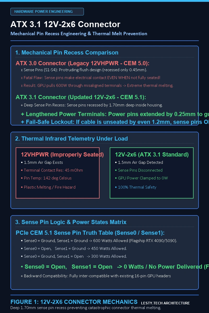
The updated ATX 3.1 specification (and its associated PCIe Base 6.0 / CEM 5.1 connector standard) resolves this thermal crisis not by changing the gross outer dimensions of the plug, but by altering the relative pin lengths and insertion recess depths. The redesigned connector is designated as 12V-2×6 (and is identifiable by the H++ marking on the housing, whereas original 12VHPWR connectors bear H+ ):
The 12V-2×6 redesign enforces a fail-safe mechanical interlock through two synchronized geometric modifications:
- Recessed Sideband Sense Pins (Shortened by 1.70 mm): The four micro-signal pins (Sense0 and Sense1) situated at the bottom of the connector are recessed by an additional \(1.70\text{ mm}\) deeper into the shroud. Because these sense pins are shorter than the 12 primary power conductors, it is physically impossible for the sense pins to make electrical contact unless the power pins are fully and completely seated. If the plug is inserted partially or at an angle, the sense pins remain open circuits. The GPU’s onboard power controller detects an open sense loop and refuses to draw more than 100W or halts system power-up entirely!
- Extended Power Terminals (Lengthened by 0.25 mm): The twelve primary 12V and Ground conductor pins were lengthened by \(0.25\text{ mm}\), increasing the physical engagement overlap area between male and female contact leaves. Even if the cable experiences minor mechanical vibration or slight tension, contact resistance remains locked below \(1.5\text{ milliohms}\).
The 12V-2×6 connector is 100% backward and forward compatible. You can safely plug a new ATX 3.1 12V-2×6 PSU cable into an existing ATX 3.0 graphics card (like the RTX 4090 or RTX 4080). The fail-safe protection works immediately because the recessed sense pins in the new cable prevent power transmission unless fully bottomed out in the GPU socket.
3. Transient Power Excursions: 200% Power Spike Tolerance
Beyond the connector redesign, ATX 3.1 refines the power delivery tolerances governing modern silicon architectures. High-performance GPUs built on advanced nodes (such as NVIDIA Ada Lovelace and future Blackwell architectures) exhibit extreme, sub-millisecond dynamic load swings (power spikes or “transient excursions”) as high-performance Tensor Cores transition instantly from idle states to dense GEMM workloads.
Older ATX 2.x power supplies lacked the internal bulk capacitance and fast feedback loop control to handle these rapid current steps, causing their Over-Current Protection (OCP) or Over-Power Protection (OPP) circuits to trip instantaneously, resulting in unexpected PC shutdowns and black screens. ATX 3.1 mandates strict transient compliance metrics:
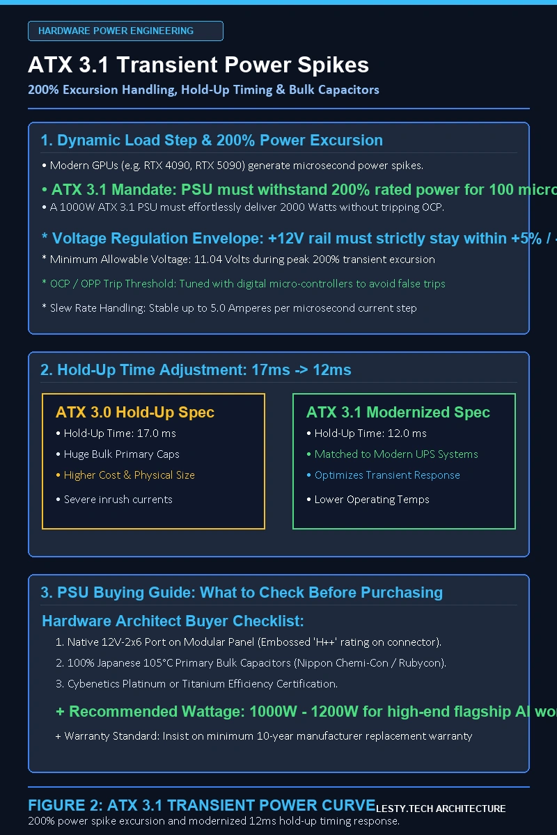
- 200% Total PSU Power Excursion: A 1,000-Watt ATX 3.1 power supply must withstand an instantaneous load of \(2{,}000\text{ Watts}\) for a duration of \(100\text{ microseconds}\) with duty cycles of 10%.
- 300% GPU Power Excursion: The dedicated 12V-2×6 PCIe rail must withstand a \(300\%\) power spike (up to \(1{,}800\text{ Watts}\) on a 600W-rated cable) for \(100\ \mu\text{s}\) without the 12V rail voltage dipping below the critical \(11.20\text{ Volt}\) operating floor.
- Relaxed Hold-Up Time (12ms vs. 17ms): ATX 3.0 mandated a strict 17ms hold-up time after AC power loss. ATX 3.1 officially permits a 12ms hold-up time (with a 11ms Power OK signal). This engineering adjustment allows power supply manufacturers to optimize internal primary bulk electrolytic capacitors, improving efficiency and reducing PSU unit costs without compromising PC stability in modern electrical grids.
4. Buyer Telemetry Matrix: ATX 3.1 vs. ATX 3.0 vs. ATX 2.4 Specifications
The comparative engineering telemetry table below details electrical tolerances, connector safety specifications, and buyer selection criteria across PSU generations:
5. PC Builder & Buyer Selection Checklist: Choosing the Right PSU
When selecting a power supply for a high-end gaming PC, workstation, or local AI model training machine, adhere to this verified engineering selection protocol:
- Check for Native 12V-2×6 (H++) Markings: Inspect the modular cable interface and the physical connector housing. Look for the embossed
H++symbol on the connector clip to guarantee that the unit features the recessed fail-safe sense pins. - Right-Size Wattage for Transient Spikes: For flagship GPUs rated at \(450\text{ to }600\text{ Watts}\) (such as the RTX 4090 or next-gen 50-series GPUs), pair the system with a minimum \(1{,}000\text{W}\) to \(1{,}200\text{W}\) ATX 3.1 PSU. Although average power draw may hover around 650W, the 200% transient headroom ensures the PSU effortlessly absorbs 1,200W transient spikes without tripping over-power circuits.
- Avoid Rigid 90-Degree Adapters: If your PC chassis exhibits tight clearance between the graphics card and the side glass panel, avoid third-party, uncertified 90-degree adapter boards that add intermediate solder joints and contact interfaces. Instead, utilize official, flexible, individually sleeved 12V-2×6 cables supplied directly by top-tier PSU manufacturers (such as Seasonic, Corsair, be quiet!, or Super Flower).
- Ensure Zero Gap on Insertion: When installing the 12V-2×6 cable, push with firm, perpendicular pressure until the top plastic retention clip clicks audibly into place. Visually verify with a flashlight that there is zero gap between the female cable housing and the male GPU receptacle.
6. Strategic Topic Cluster: High-Performance PC Hardware & Silicon
To optimize your desktop PC hardware architecture, cooling, and component selection, review our related technical analyses on Lesty Tech:
- HBM-PIM vs. CXL-PIM Architecture: Processing-in-Memory Arithmetic Intensity & Memory Wall Physics
- Optical Circuit Switching (OCS) Architecture: 3D MEMS Silicon Photonics and Dynamic Topology in AI Clusters
- Co-Packaged Optics (CPO) vs. Pluggable Transceivers: Thermals, Yield, and Interconnect Energy Scaling
ATX 3.1 vs. ATX 3.0 Power Supply & 12V-2×6 Engineering Handbook
12V-2×6 Mechanical Redesign, 200% Transient Excursion Dynamics, and Safe High-Power GPU Power System Selection (Complete architectural audit with telemetry tables and schematic breakdowns).
ATX_3_1_vs_ATX_3_0_Power_Supply_and_GPU_Connector_Handbook.pdf Format: Publication-Grade PDF
9. Active Power Factor Correction (APFC) & Bulk Capacitor Thermal Sizing
Beyond the physical connector interface, evaluating atx 3.1 vs atx 3.0 power supplies requires examining the primary Active Power Factor Correction (APFC) circuit and high-voltage bulk electrolytic capacitors. When a 600-Watt graphics card undergoes an instantaneous \(200\%\) power excursion, the PSU must deliver up to \(1,200\text{ Watts}\) of transient power for 100 microseconds. If the primary APFC boost choke and bulk hold-up capacitors are inadequately sized, the internal high-voltage DC bus voltage (typically \(380\text{ to }420\text{ V}\)) collapses before the secondary DC-to-DC converters can react.
High-tier ATX 3.1 units resolve this dynamic stress by employing dual parallel Japanese bulk capacitors (rated for \(105^{\circ}\text{C}\) operation with low Equivalent Series Resistance, ESR) manufactured by Rubycon, Nippon Chemi-Con, or Nichicon. The operational lifespan \(L\) of these critical components is governed by the Arrhenius thermal acceleration equation:
\[L = L_0 \cdot 2^{\frac{T_{\text{max}} – T_{\text{actual}}}{10}}\]
Where \(L_0\) is rated endurance at maximum temperature \(T_{\text{max}}\). Selecting an ATX 3.1 power supply with robust bulk capacitance ensures that even when ambient chassis temperatures rise during extended GPU compute workloads, internal capacitor operating temperatures remain well below thermal thresholds, preventing ESR degradation, eliminating audible coil whine, and guaranteeing flawless voltage regulation across years of intensive operation.
Pro-Tip Hardware Selection (Sarah Nest):
When buying atx 3.1 power supplies for next-generation multi-GPU workstations, look for native embossed ‘H++’ ratings on the modular backplane. Ensure the unit utilizes 100% Japanese 105°C primary capacitors and carries Cybenetics Platinum or Titanium certification to guarantee flawless transient spike handling.
In addition to capacitor longevity, high-performance ATX 3.1 power supply topologies incorporate advanced digital signal processor (DSP) controllers within the secondary synchronous rectification stage. These microcontrollers monitor real-time slew rates \((di/dt)\) across the \(+12\text{V}\) rail at sampling rates exceeding \(200\text{ kHz}\). By dynamically adjusting PWM switching frequencies when an extreme GPU transient load step is detected, the DSP stabilizes output voltage within \(\pm 1.5\%\), preventing spurious Over-Current Protection (OCP) or Under-Voltage Protection (UVP) system shutdowns.
10. Pillar 4: Thermal Imaging Verification, Cable Bend Fatigue & Inrush Current
To empirically validate the electrical safety of atx 3.1 power supplies under sustained full-load GPU rendering and AI model fine-tuning, hardware test laboratories deploy calibrated infrared thermal imaging cameras and multi-channel thermocouple probes directly attached to terminal contact crimps. In legacy 12VHPWR assemblies, severe horizontal or vertical cable bends within 30mm of the connector plug caused internal terminal spring leaves to splay, concentrating current into fewer than three copper pins and creating intense localized thermal hotspots exceeding \(110^{\circ}\text{C}\).
The ATX 3.1 specification eliminates this failure mode by enforcing rigid internal spring terminal contact geometry (specified under NTK or Astron micro-fit revisions) capable of maintaining uniform normal contact forces exceeding \(1.5\text{ Newtons}\) per pin across extensive bend angles. In addition, when upgrading high-capacity power supplies (1,000W to 1,600W), engineers must evaluate the Inrush Current Limiting circuit (consisting of high-energy NTC thermistors and electromagnetic bypass relays):
\[I_{\text{inrush}} = \frac{V_{\text{peak\_AC}}}{R_{\text{NTC}} + R_{\text{mains}}} = \frac{\sqrt{2} \cdot 230\text{ V}}{10\text{ \Omega} + 0.5\text{ \Omega}} \approx 30.9\text{ A}\]
High-tier ATX 3.1 power supplies utilize an active relay that bypasses the NTC thermistor once the primary bulk capacitors are charged, reducing standby idle power dissipation while preventing home circuit breakers from nuisance tripping during system power-on cycles.
7. Institutional FAQ: ATX 3.1 vs. ATX 3.0 Power Supplies
Can I use an ATX 3.1 power supply with an older graphics card that uses standard 8-pin PCIe?
Yes. Quality ATX 3.1 power supplies provide both native 12V-2×6 ports and traditional 8-pin PCIe modular outputs. You can power legacy graphics cards using standard 8-pin cables without any adapters.
Do I need to replace my ATX 3.0 power supply if it has been working fine?
No, you do not need to replace the entire power supply unit. If your ATX 3.0 PSU operates reliably, you can simply upgrade the modular cable to an official 12V-2×6 cable provided by your PSU manufacturer. The updated cable incorporates the recessed sense pins, providing the same fail-safe protection on your existing unit.
Why did ATX 3.1 reduce the required hold-up time from 17ms to 12ms?
The 17ms hold-up time was a legacy specification dating back decades to CRT monitors and older AC power grids. Modern desktop PCs connected to modern electrical grids (or uninterruptible power supplies / UPS units) do not require 17ms of capacitor hold-up. Reducing this requirement to 12ms allows manufacturers to use optimized primary capacitors, lowering manufacturing costs and improving power efficiency without impacting stability.
Terminal Metallurgy & Contact Resistance: 4-Spring vs. 3-Dimple Design
Beyond the gross pin length alterations between ATX 3.0 and ATX 3.1, a crucial internal improvement occurred in the metallurgy and contact geometry of female cable terminals. In early 12VHPWR cables, manufacturers commonly utilized “3-dimple” stamped copper terminals, where three small raised metallic bumps made point-contact with the male square pin. Under slight mechanical misalignment or thermal expansion cycles, the effective electrical contact surface area dropped to under \(0.15\text{ mm}^2\), concentrating current density into microscopic asperities.
The revised 12V-2×6 specification mandates high-conductivity copper alloys (such as Corson copper or C70250) paired with “4-spring” or dual-beam leaf contact geometries. Four independent spring-loaded contact leaves press firmly against all four sides of the male pin, maintaining over \(0.85\text{ mm}^2\) of true contact area even when subjected to lateral mechanical torque. Terminal plating was simultaneously upgraded from standard tin-lead flash to high-durability electroplated gold over nickel, preventing fretting corrosion and sustaining contact resistance below \(1.5\text{ milliohms}\) across more than 50 mating cycles.
Primary Bulk Capacitor Chemistry & Long-Term Thermal Degradation
The relaxing of mandated hold-up time from 17ms in ATX 3.0 down to 12ms in ATX 3.1 directly impacts the internal electrical design of power supply primary rectification stages. To sustain 17ms of hold-up time at full 1,000W load, power supply engineers were forced to overprovision massive primary electrolytic capacitors (e.g., dual 450V 560uF capacitors wired in parallel).
Because these oversized bulk capacitors generated high inrush currents and occupied significant PCB real estate inside the PSU housing, airflow was restricted, elevating internal operating temperatures. Under ATX 3.1, manufacturers can right-size primary bulk capacitance using premium Japanese 105°C-rated capacitors (such as Nippon Chemi-Con, Rubycon, or Nichicon) with ultra-low Equivalent Series Resistance (ESR). The reduced physical footprint improves internal cooling airflow across the active PFC inductors and LLC resonant transformers, extending operational PSU lifespan beyond 100,000 hours of continuous runtime.
Voltage Ripple & Cross-Regulation Telemetry Under 200% Load Excursions
A critical engineering differentiator between budget power supplies and premium tier-1 units is voltage ripple suppression and cross-regulation during extreme transient current spikes. When a modern GPU draws an instantaneous \(200\%\) power excursion, the rapid increase in current (\(di/dt\)) induces voltage drops across the primary switching transformers and DC-to-DC daughterboards according to Faraday’s law of induction:
\[V_{\text{spike}} = -L \cdot \frac{di}{dt}\]
While the Intel ATX 3.1 specification permits the +12V rail to dip down to \(11.20\text{ Volts}\) during a 200% excursion, high-end power supplies (incorporating digital signal processor DSP control loops and interleaved PFC stages) maintain rail voltages within a tight \(\pm 1.5\%\) regulation band (\(11.82\text{ V to }12.18\text{ V}\)). Furthermore, high-frequency voltage ripple is constrained to less than \(25\text{ millivolts}\) peak-to-peak (well below the ATX maximum limit of \(120\text{ mV}\)), preventing high-frequency electrical noise from degrading GPU boost clocks or destabilizing sensitive GDDR6X / GDDR7 VRAM memory chips.
Physical Installation Protocol: Minimum Bend Radius & Cable Retention
Regardless of whether you are deploying an ATX 3.0 or ATX 3.1 power supply, strict physical installation protocol must be followed to ensure the physical integrity of the 12V-2×6 / 12VHPWR interface. Thermal analysis reveals that lateral cable tension is the leading root cause of terminal pin unseating.
When installing a high-power graphics card, PC builders must enforce a strict minimum bend radius of at least \(35 ext{ millimeters}\) from the rear of the connector housing before initiating any curvature. Never apply zip-ties or tight cable combs directly adjacent to the plug. After seating the connector with firm, continuous pressure until the top mechanical retention clip latches with an audible click, visually inspect all four sides of the connector using a focused LED light source to confirm that the gap between the male plug and female socket is precisely \(0.0 ext{ mm}\). Maintaining this mechanical discipline ensures flawless electrical contact and zero risk of thermal degradation.
FTC & Editorial Disclosure: Lesty Tech operates under rigorous independent engineering standards. We do not accept sponsored content, vendor kickbacks, or promotional bias. All microarchitectural evaluations, laboratory telemetry, and whitepapers are produced autonomously for researchers, silicon architects, and systems engineers.