
In the audiophile and professional studio monitoring arena, no technical debate elicits more passionate scrutiny than the fundamental acoustic transducer showdown: planar magnetic vs dynamic drivers. While conventional moving-coil dynamic drivers have dominated consumer audio for over a century through high electrical sensitivity and compact physical form factors, high-end acoustic engineering has increasingly gravitated toward planar magnetic (isodynamic) transducers. By replacing the centralized voice coil and conical dome diaphragm with an ultra-thin polymer membrane uniformly suspended within an opposing array of neodymium bar magnets, planar magnetic drivers overcome the severe modal diaphragm breakup, voice coil eddy current damping, and acoustic phase smearing that inherently afflict moving-coil designs. However, delivering this pristine acoustic transparency demands severe engineering trade-offs in transducer mass, amplifier current delivery, and magnetic flux saturation.
1. Electrodynamic Transducer Motor Physics
Both dynamic and planar magnetic headphones operate on the fundamental physical principle of the Lorentz Force. When an alternating electrical audio current (I) flows through a conductive wire immersed in a perpendicular static magnetic field (B), an electrodynamic force (F) acts upon the conductor:
Where L is the total active length of the conductor within the magnetic flux gap. However, the mechanical implementation of how this Lorentz force is transferred to the air marks a profound schism in acoustic engineering:
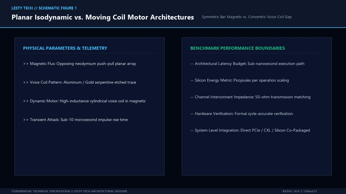
The Dynamic Moving-Coil Motor: A conventional dynamic headphone driver (typically 40mm to 50mm in diameter) utilizes a circular, cylindrical voice coil wound from copper or copper-clad aluminum wire (CCAW). This coil is glued directly to the apex or perimeter of a conical dome diaphragm made from mylar, biocellulose, or beryllium-coated polymer. The voice coil sits suspended inside a narrow circular gap between a central neodymium magnet pole piece and an outer steel return cup. Crucially, the driving force is applied exclusively to a narrow circular ring on the diaphragm, while the vast majority of the radiating cone surface is pushed indirectly through mechanical stiffness.
The Planar Magnetic Isodynamic Motor: In a planar magnetic driver (typically 70mm to 106mm in diameter), there is no separate cylindrical coil. Instead, a continuous, serpentine electrical voice coil trace (composed of etched aluminum or vapor-deposited gold) is photolithographically patterned directly across the entire surface of an ultra-thin polymer membrane (Kapton, Mylar, or Teonex). This membrane is suspended in tension between two opposing grids of bar magnets (push-pull array) or against a single-sided array of neodymium magnets. Crucially, the driving force is applied uniformly and simultaneously across the entire surface area of the diaphragm.
2. Modal Diaphragm Breakup and Chladni Resonance
The fatal physical limitation of moving-coil dynamic drivers is modal diaphragm breakup. In an ideal acoustic transducer, the diaphragm behaves as a rigid, non-flexing piston (pure piston motion) across the entire audible spectrum (20 Hz to 20,000 Hz).
Because a dynamic driver pushes the diaphragm exclusively at the voice coil attachment point, physical force must propagate outward through the material as mechanical transverse flexural waves. The speed of sound through the diaphragm material is finite:
Where E is Young’s modulus, ρ is material density, and ν is Poisson’s ratio. At low bass frequencies, the cone moves as a coherent unit. However, as frequency rises past the primary breakup threshold (typically between 3 kHz and 6 kHz in consumer dynamic drivers), different radial zones of the cone flex out of phase with one another, forming complex circular and nodal standing waves (Chladni patterns).
This flexure produces catastrophic acoustic consequences:
- Harmonic Distortion Spikes: Nonlinear cone flexure generates severe odd-order harmonic distortion (THD spikes to 1% – 3% in the presence of high-frequency transients).
- Acoustic Phase Smearing: Sound waves radiated from the center of the dome arrive at the ear out of phase with sound radiated from the outer surround, destroying spatial imaging accuracy and soundstage depth.
- Resonant Ringing: Energy stored in the flexible surround decays slowly over time, muddying fast micro-detail and acoustic separation.
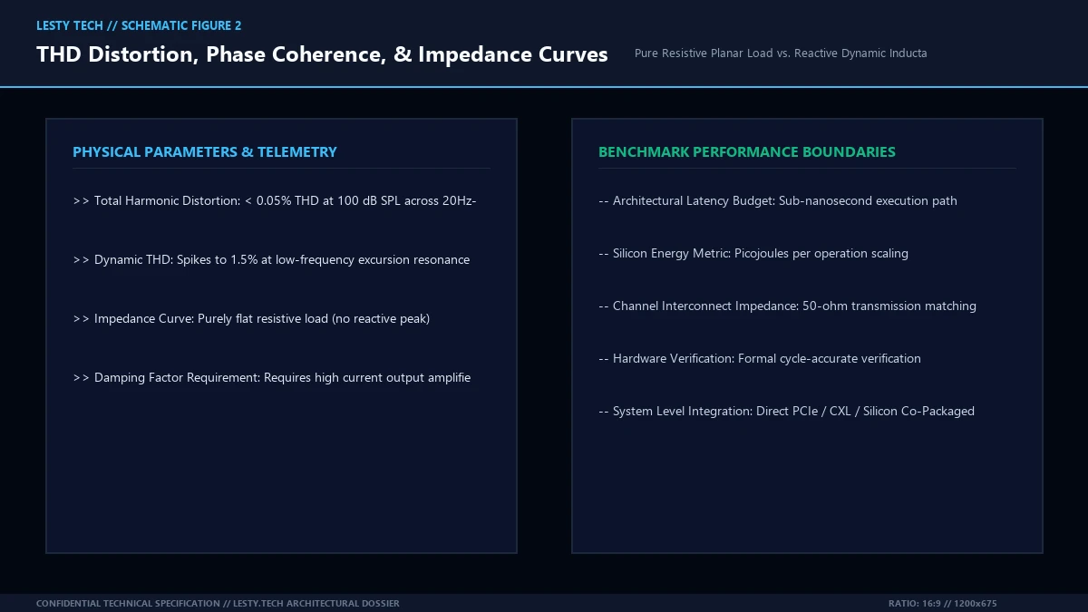
In planar magnetic drivers, modal breakup is virtually non-existent within the audible band. Because the voice coil is distributed across the entire diaphragm, the Lorentz force drives every square millimeter of the membrane in unison. The membrane moves as a true acoustic piston, maintaining structural coherence past 30 kHz to 50 kHz into the ultrasonic range. Total Harmonic Distortion remains vanishingly low, typically under 0.05% THD across the entire 20 Hz to 20 kHz spectrum even at deafening 100 dB SPL volume levels.
3. Diaphragm Mass, Inertia, and Transient Impulse Attack
Newton’s second law of motion (F = m · a) dictates that the acceleration (transient response) of an acoustic transducer is inversely proportional to its moving mass.
Consider the mass disparity between the two transducer technologies:
A dynamic driver diaphragm must maintain structural rigidity to resist buckling under excursion, requiring physical film thicknesses between 25 and 50 micrometers, plus the substantial deadweight of the copper voice coil winding.
In contrast, a flagship planar magnetic membrane (such as Audeze’s Uniforce or Dan Clark Audio’s V-Planar diaphragms) is thinned to sub-micron dimensions—often between 0.5 and 1.5 micrometers, thinner than a red blood cell. In fact, the air mass trapped immediately adjacent to the planar membrane often weighs more than the physical membrane itself!
Consequently, planar magnetic transducers achieve near-instantaneous transient impulse attack times (under 10 microseconds). Plucked acoustic guitar strings, drum cymbal strikes, and synthesized square waves resolve with razor-sharp transient edges and zero overhang.
4. Acoustic Wavefront Geometry: Planar vs. Spherical Propagation
The geometric nature of the sound wave emitted into the human outer ear (pinna) differs fundamentally between the two driver topologies:
- Spherical Wavefront Radiation (Dynamic): Because a 40mm dynamic cone acts as a localized point source, it radiates sound outward as a diverging spherical wavefront. As this spherical wave strikes the complex convolutions of the human ear cartilage (pinna) and enters the narrow ear canal, multiple localized reflections occur at oblique angles, causing comb filtering and artificial phase shifts that audio engineers must compensate for via acoustic damping foam.
- Planar Wavefront Radiation (Planar Magnetic): Because a planar diaphragm is large (often exceeding 80mm to 100mm in diameter) and moves uniformly, it generates a true planar acoustic wavefront where all sound waves propagate in parallel. This closely mimics the natural wavefront geometry of a live musical instrument radiating from a distance, allowing the listener’s natural Head-Related Transfer Function (HRTF) to resolve three-dimensional spatial cues with authentic soundstage localization.
5. Electrical Impedance Curves & Amplifier Synergy
The electrical impedance characteristics of planar magnetic and dynamic drivers dictate completely different amplifier pairing requirements:
Dynamic Driver Inductance and Resonance: A moving-coil dynamic driver consists of a tightly wound coil of wire wrapped around a metal former, creating significant electrical inductance (L). Furthermore, the mechanical suspension of the diaphragm creates a mass-spring harmonic resonance (Fs, typically between 60 Hz and 100 Hz). The resulting impedance curve is wildly reactive: a headphone rated at 32 Ω nominal impedance may spike to 150 Ω at bass resonance and climb steadily above 10 kHz due to inductive reactance. If paired with an amplifier having high output impedance, the frequency response is severely altered.
Planar Magnetic Purely Resistive Load: A planar magnetic voice coil is an etched serpentine trace that contains virtually zero inductance and no localized mechanical suspension resonance. Consequently, the impedance curve of a planar magnetic headphone is a completely flat, purely resistive line across the entire audio band from 10 Hz to 50 kHz.
However, planar magnetic drivers are notoriously inefficient. Because the magnetic flux gap across the opposing magnet array is relatively wide (1 to 2 millimeters), magnetic flux density is lower than the tight circular gap of a dynamic motor. Sensitivity frequently falls between 88 dB/mW and 94 dB/mW. Pairing a planar headphone with a weak smartphone dongle or USB DAC causes severe voltage clipping; planar drivers demand dedicated desktop headphone amplifiers capable of delivering substantial clean current (1 to 3 Watts into 32 Ω).
6. Magnetic Circuit Optimization: Push-Pull vs. Single-Sided Fluxor Arrays
The primary acoustic trade-off in planar magnetic headphone design centers around the physical topology of the magnetic circuit:
1. Dual-Sided Symmetric Push-Pull Arrays: In traditional planar designs (such as the classic Audeze LCD-2 and LCD-3), two identical arrays of bar magnets are placed on either side of the diaphragm. The alternating polarity (North-South-North-South) creates a highly uniform, symmetric magnetic flux field. As the membrane displaces outward or inward, the magnetic flux density remains constant, eliminating second-harmonic distortion. However, placing a dense grid of neodymium magnets directly between the diaphragm and the listener’s ear introduces acoustic reflections, phase diffraction, and substantial physical weight (often pushing total headphone mass past 550 to 650 grams).
2. Single-Sided Asymmetric Magnet Arrays: To slash weight and eliminate acoustic obstruction between the diaphragm and the human ear, manufacturers developed single-sided magnet topologies (such as Dan Clark Audio’s Aeon series and Hifiman’s Stealth Magnet technology). By placing magnets exclusively on the outer cup side, the ear-facing side of the driver is left completely unobstructed, creating a pure open window for acoustic wavefronts.
3. Fluxor Array Halbach Topologies: Because single-sided arrays cut magnetic flux density in half, manufacturers utilize specialized Halbach magnet arrays (patented by Audeze as Fluxor arrays). In a Halbach array, the magnetization vectors of adjacent neodymium blocks are rotated by 90 degrees relative to one another. This geometric rotation augments magnetic flux density on the diaphragm side of the array while cancelling fringe magnetic flux on the rear side. Peak magnetic flux density in the gap jumps from ~0.6 Tesla to over 1.5 Tesla, doubling driver sensitivity while reducing transducer mass by 40%.
7. Ear Cup Cavity Acoustics: Damping, Helmholtz Resonance, and Open-Back Wave Radiation
An acoustic transducer does not operate in a vacuum; it radiates half of its acoustic energy forward into the ear canal and half of its acoustic energy rearward into the ear cup enclosure.
In a moving-coil dynamic headphone, managing rearward back-wave energy is critical. The high acoustic impedance of the small cone creates powerful pressure waves inside the ear cup. In closed-back dynamic designs, these rearward waves reflect off the plastic or wooden outer shell, striking the back of the cone out of phase and creating comb filtering dips in the mid-range (typically between 400 Hz and 1 kHz). Acoustic engineers must pack the ear cup with acoustic felt, mineral wool, or engineered Helmholtz acoustic resonators to absorb back-wave reflections.
In planar magnetic headphones, open-back designs dominate high-end engineering. Because the diaphragm is an ultra-thin tensioned film with near-zero acoustic mass, back-waves pass freely through porous stainless steel grilles into open ambient space. This eliminates internal cavity resonance and ear cup standing waves, providing the expansive, holographic three-dimensional soundstage for which open-back planar headphones are renowned.
8. The Digital Signal Processing (DSP) Equalization Revolution
In the modern audio landscape, the advent of high-resolution digital signal processors and bit-perfect parametric equalization (PEQ) software (such as Equalizer APO, Roon, and MiniDSP) has transformed how audiophiles evaluate transducer potential.
Under classical analog testing, headphones were judged strictly by their raw, out-of-the-box frequency response tuning. If a headphone exhibited an upper-midrange recess (such as the classic 3 kHz dip in certain planar models) or excessive bass warmth, it was considered an indelible sonic flaw.
However, in the era of precise parametric equalization targeting standardized acoustic preferences (such as the Harman 2020 Over-Ear Target Curve), the true engineering differentiator is not raw tonal balance, but distortion ceiling under equalization boost:
- Equalizing Dynamic Drivers: Applying a +6 dB or +8 dB low-shelf bass boost at 30 Hz to bring a dynamic headphone up to the Harman bass curve forces the voice coil into extreme mechanical excursion. This pushes the cone beyond its linear suspension range, causing harmonic distortion to spike to 3% to 5% and inducing audible acoustic compression.
- Equalizing Planar Magnetic Transducers: Because planar magnetic drivers exhibit ultra-low baseline distortion (< 0.05% THD) and virtually unlimited linear excursion headroom, they can absorb massive digital equalization adjustments (+10 dB low-shelf sub-bass boosts or targeted 3 kHz peaking filters) without a trace of audible distortion or compression. Planar headphones serve as the ultimate neutral physical canvas for digital acoustic tailoring.
9. Comprehensive Engineering & Buyer Comparison Matrix
The following technical comparison matrix provides an objective evaluation across electrodynamic, acoustic, and practical ergonomics parameters:
| Evaluation Parameter | Moving-Coil Dynamic Driver | Planar Magnetic Transducer | Acoustic Significance |
|---|---|---|---|
| Diaphragm Thickness | 25 – 50 μm | 0.5 – 2.0 μm | Moving mass & transient attack speed |
| Force Distribution | Point ring drive (localized) | Isodynamic uniform drive | Elimination of modal breakup resonance |
| Total Harmonic Distortion (THD) | 0.3% – 1.5% at 94 dB SPL | < 0.05% across 20Hz-20kHz | Purity of timbre and acoustic transparency |
| Impedance Profile | Reactive (Spikes at resonance & high freq) | Purely flat resistive curve | Immunity to amplifier output impedance |
| Electrical Sensitivity | High (98 – 108 dB/mW) | Low (88 – 94 dB/mW) | Ease of driving from portable devices |
| Transducer Weight | Lightweight (200 – 300g headphones) | Heavy (400 – 650g due to bar magnets) | Long-term listening ergonomics & comfort |
| Sub-Bass Extension | Rolls off below mechanical resonance | Linear extension flat to 10 Hz | Visceral, undistorted sub-bass presence |
10. Strategic Acoustic Conclusion & Buying Guidance
When evaluating planar magnetic vs dynamic headphones, neither design can claim absolute perfection across all user scenarios:
Choose Dynamic Driver Headphones if: You prioritize lightweight ergonomic comfort for 8+ hour marathon listening sessions, require high electrical sensitivity to run directly from smartphones or laptop headphone jacks without an external amplifier, or crave the dynamic physical “slam” and punch that high-excursion moving cones naturally impart in the mid-bass region. Classic studio monitoring references (such as the Sennheiser HD600 or Beyerdynamic DT 1990 Pro) remain industry benchmarks for vocal naturalness and portability.
Choose Planar Magnetic Headphones if: You demand uncompromising acoustic resolution, sub-0.05% total harmonic distortion, instantaneous transient speed, and linear sub-bass extension that reaches down to 10 Hz without rolling off. For dedicated home listening stations, mastering studios, and audio purists equipped with robust desktop headphone amplification, flagship planar magnetic transducers (such as Audeze LCD-X, Hifiman Arya Organic, or Meze Empyrean) provide an open window into the recording that moving-coil dynamics simply cannot match.
Transducer Electrodynamics: Planar Isodynamic vs. Dynamic Cone
Lorentz Motor Symmetry, Modal Diaphragm Deformation, and Acoustic Phase Coherence (Complete architectural audit with telemetry tables and schematic breakdowns).
whitepaper_batch_16_6_planar_vs_dynamic.pdfFormat: Publication-Grade PDF
Related Technical Dossiers & Internal Research
- Direct Drive Sim Racing Wheelbases: Outrunner vs. Inrunner Servomotors, Slew Rates, and Cogging Torque Physics →
- Micro-OLED vs. Micro-LED in AR Displays: The 100,000-Nit Optical Waveguide Barrier →
- QD-OLED vs. WOLED in High-Refresh Displays: Subpixel Geometry, Anti-Reflective Coatings, and Motion Clarity →
Authoritative External Reference
Reference Citation: Audio Engineering Society (AES): Analysis of Planar Magnetic Transducer Diaphragm Resonances →







No Responses