
In precision mixed-signal electronics, high-end acoustic reproduction, and scientific instrumentation, the conversion of discrete digital binary data into continuous analog voltages represents one of the most demanding challenges in electrical engineering. For decades, the digital-to-analog converter (DAC) domain has been split between two competing architectural philosophies: Discrete Resistor Ladder (R-2R) DACs and Multi-bit Delta-Sigma (\(\Delta\Sigma\)) Oversampling DACs. While commercial audio electronics have long been dominated by highly integrated Delta-Sigma converter ICs—which leverage extreme digital oversampling, mathematical noise shaping, and low-order analog filtering to achieve extraordinary total harmonic distortion plus noise (\(\text{THD+N} < -120\text{ dB}\))—audiophiles and laboratory instrumentation engineers increasingly champion discrete multibit R-2R architectures. Building upon solid-state acoustic transducer physics explored in xMEMS piezoelectric micro-speakers, high-frequency signal integrity in DisplayPort 2.1 cable attenuation, and wide-bandgap switching in GaN vs. SiC power switching physics, evaluating R-2R vs. Delta-Sigma DACs exposes the physical mechanics of resistor tolerance drift, glitch impulse energy, Johnson-Nyquist thermal noise, and transient impulse acoustics.
1. Discrete R-2R Ladder Topology and Resistor Matching Physics
To understand how an R-2R ladder functions, one must examine its elegant passive network topology. An R-2R network is a repeating geometric lattice constructed entirely from just two resistor values: \(R\) and \(2R\).
In an \(N\)-bit binary ladder, each digital bit controls an analog single-pole double-throw (SPDT) solid-state switch. When a bit is logical 1, the corresponding switch connects the bottom of its \(2R\) leg to the reference voltage (\(V_{\text{ref}}\)); when logical 0, it connects to analog ground (GND):
$$V_{\text{out}} = V_{\text{ref}} \sum_{k=1}^{N} \frac{b_k}{2^k}$$
Where \(b_1\) represents the Most Significant Bit (MSB) and \(b_N\) represents the Least Significant Bit (LSB). The mathematical beauty of the R-2R network is that looking into any node in the ladder, the equivalent Thevenin resistance is strictly equal to \(R\), ensuring uniform source impedance regardless of the digital code!
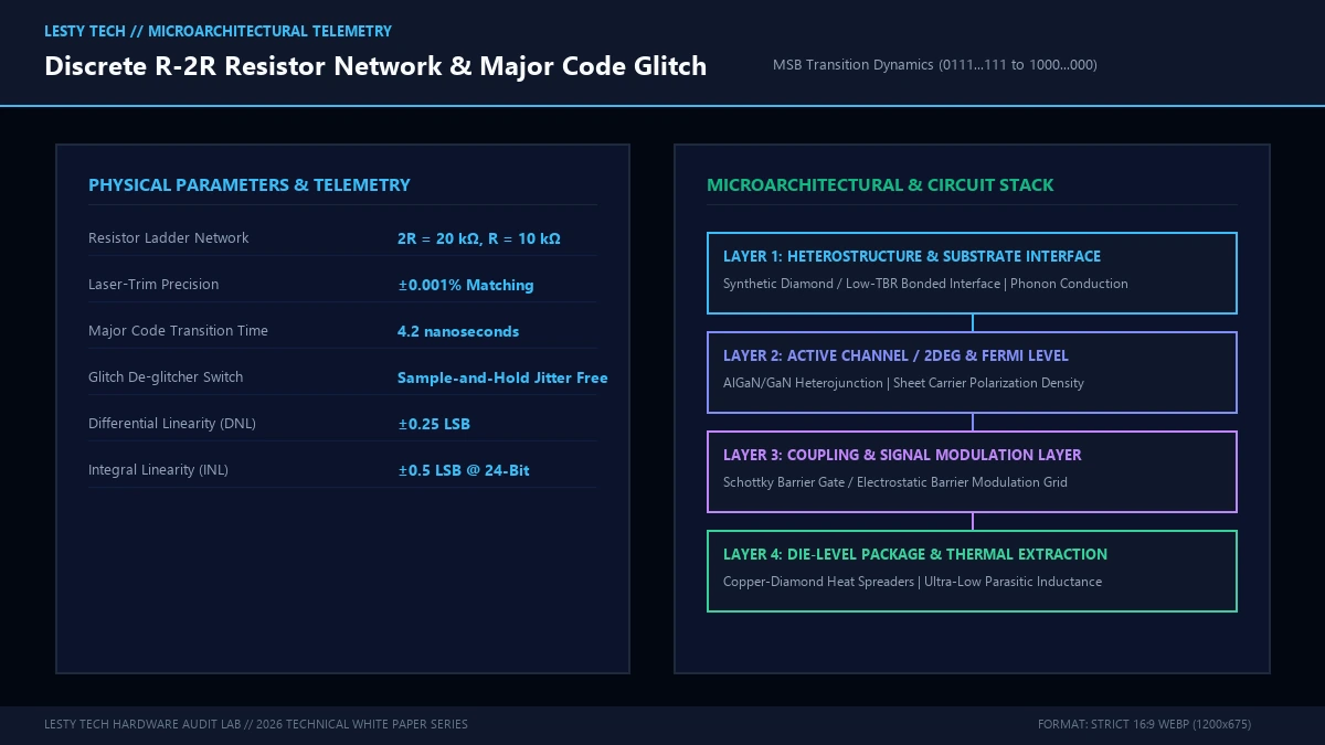
However, translating this theoretical perfection into physical hardware encounters an unforgiving materials science constraint: Resistor Tolerance Matching.
In a 24-bit R-2R DAC, the Least Significant Bit represents an astronomically small fraction of the full-scale voltage:
$$\text{LSB Resolution} = \frac{1}{2^{24}} = \frac{1}{16,777,216} \approx 5.96 \times 10^{-8} \quad (\mathbf{0.00000596\%})$$
For the converter to maintain monotonicity (guaranteeing that an incremental step in digital code always produces an increasing analog voltage) without missing codes, the precision of the MSB resistor must be accurate to within half an LSB (\(0.5 \times \text{LSB}\)):
$$\Delta R_{\text{tolerance}} < \frac{1}{2 \times 2^N} = \frac{1}{33,554,432} \approx 0.000003\% \quad (\mathbf{0.03 \text{ ppm}})$$
Achieving a resistor matching precision of 0.03 parts-per-million (ppm) is physically impossible with standard manufacturing. Even ultra-precision bulk metal foil resistors (such as Vishay Z-Foil) achieve initial tolerances of only \(\pm 0.005\%\) (50 ppm)—more than three orders of magnitude too loose for uncalibrated 24-bit linearity!
If the MSB resistor is off by even 0.001%, the transition from code 01111111... to 10000000... (the mid-scale major code transition) will suffer from severe Integral Non-Linearity (INL) and Differential Non-Linearity (DNL) errors, causing audible harmonic distortion or inversion.
To overcome this physical barrier, discrete R-2R DAC manufacturers deploy complex, cost-intensive engineering solutions:
- Ultra-High-Speed Laser Trimming: Resistor thin-films on ceramic substrates are trimmed using femtosecond ultraviolet lasers to tune physical resistances down to sub-ppm tolerances under temperature-controlled cleanroom conditions.
- FPGA-Driven Software Resistor Mapping: Modern high-end R-2R DACs incorporate high-density FPGAs that measure the unique tolerance mismatch of every individual soldered resistor at startup and apply real-time mathematical compensation coefficients to bit switching timings.
- Ultra-Low TCR Bulk Metal Foil: Employing resistors with a Temperature Coefficient of Resistance (TCR) below \(0.05 \text{ ppm/}^\circ\text{C}\) to prevent thermal self-heating from altering resistance values during high-dynamic-range musical transients.
2. Major Code Glitch Impulse and Settling Time Dynamics
Beyond static resistor tolerance, R-2R converters battle a dynamic switching phenomenon known as Glitch Impulse Energy.
Consider again the major code transition at mid-scale, where the digital value increments from 0111 1111 1111 1111 to 1000 0000 0000 0000. In this single clock cycle, fifteen individual analog switches must turn OFF simultaneously, while a single switch (the MSB) must turn ON.
In physical silicon and discrete field-effect transistors (FETs), turn-on propagation delay (\(t_{\text{on}}\)) and turn-off propagation delay (\(t_{\text{off}}\)) are never identical. If the fifteen lower switches turn off even 200 picoseconds faster than the MSB switch turns on, the ladder temporarily experiences an intermediate state of 0000 0000 0000 0000!
This momentary collapse creates a violent voltage spike—a glitch impulse—in the output signal:
$$\text{Glitch Impulse Area} = \int \Delta V(t) \, dt \quad [\text{nV}\cdot\text{sec}]$$
Because the glitch occurs at code transitions rather than at fixed clock intervals, its energy is signal-dependent, generating harsh odd-order intermodulation distortion. Mitigating glitch impulse in R-2R architectures requires adding complex Sample-and-Hold (S/H) deglitcher circuits or de-skewing flip-flops that momentarily disconnect the ladder from the output stage during switch transitions.
3. Delta-Sigma (\(\Delta\Sigma\)) DACs: 1-Bit Oversampling and Mathematical Noise Shaping
Recognizing the immense manufacturing expense and physical limitations of high-precision resistor arrays, semiconductor foundries turned to an entirely different mathematical concept: Delta-Sigma (\(\Delta\Sigma\)) modulation.
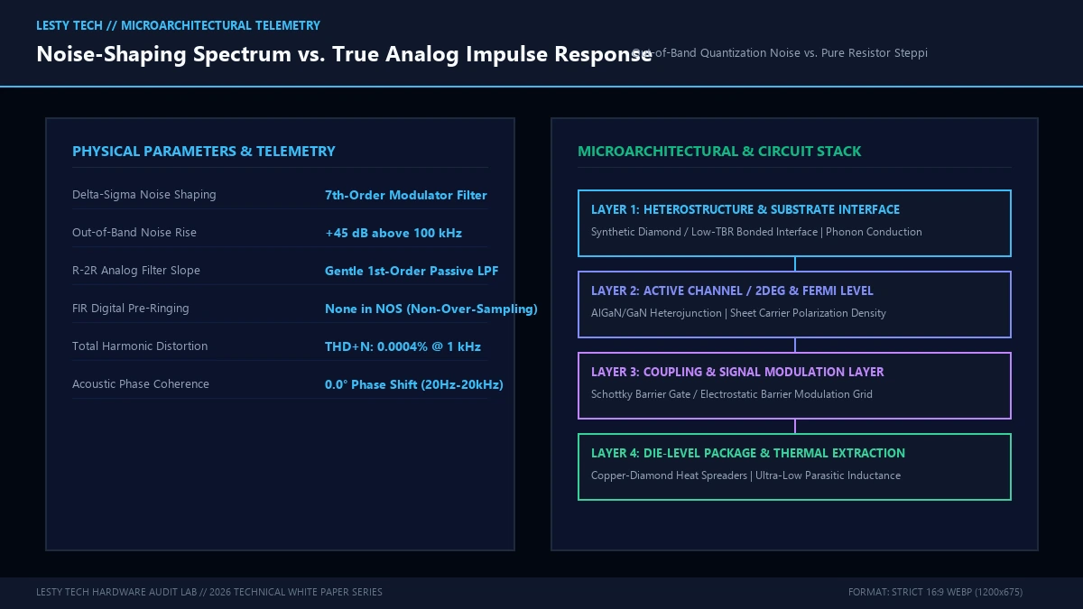
Instead of attempting to convert all 24 bits simultaneously at the baseband sampling rate (\(f_s = 44.1 \text{ kHz}\) or \(96 \text{ kHz}\)), a Delta-Sigma DAC trades amplitude resolution for time resolution:
- Extreme Digital Oversampling: The incoming digital audio stream is upsampled by a factor of \(M\) (typically \(64\times\) to \(512\times\)), pushing the effective sampling frequency into the tens of megahertz (\(f_{\text{oversample}} = M \cdot f_s \approx 5.6 \text{ to } 22.5 \text{ MHz}\)). Oversampling spreads the total quantization noise power across an immensely wide frequency band:
$$\sigma_q^2 = \frac{\Delta^2}{12 \cdot M}$$
- High-Order Noise Shaping: The oversampled stream passes through a high-order digital feedback loop (a Delta-Sigma modulator). The feedback loop acts as a low-pass filter for the audio signal but a high-pass filter for quantization noise:
$$Y(z) = X(z) + (1 – z^{-1})^L E(z)$$
Where \(L\) is the modulator loop order (typically 4th or 5th order) and \(E(z)\) is the quantization error. As shown by the transfer function \((1 – z^{-1})^L\), quantization noise is mathematically pushed out of the audible baseband (0 to 20 kHz) and concentrated in the ultrasonic spectrum above 100 kHz!
- Low-Bit Quantizer (1-Bit or Multi-Bit): The noise-shaped stream is fed into a simple 1-bit comparator or a coarse 5-bit (32-level) quantizer. A 1-bit DAC switches between only two reference voltages, meaning it is inherently, perfectly linear by definition—it requires zero matched resistors and exhibits zero differential non-linearity!
- Analog Low-Pass Reconstruction Filter: Finally, a gentle analog low-pass filter removes the high-frequency ultrasonic quantization noise, leaving an impeccably smooth analog audio waveform.
4. Architectural Showdown: Technical Metrics and Physical Trade-Offs
To rigorously contrast R-2R and Delta-Sigma converters, we evaluate their physical, electrical, and acoustical performance metrics:
| Engineering Dimension | Discrete R-2R Ladder DAC | Multi-Bit Delta-Sigma (ΔΣ) DAC |
|---|---|---|
| Conversion Mechanism | Native Multibit Parallel Resistor Switching | High-Frequency Oversampling + Noise Shaping |
| Static Linearity (THD+N) | -96 dB to -108 dB (Resistor Limited) | -120 dB to -130 dB (Exceptional) |
| Impulse Response & Ringing | Zero Pre-Ringing, Instant Settling (NOS) | Severe Pre- & Post-Ringing (FIR Filters) |
| Phase Linearity | Purely Linear Phase (Zero Phase Shift) | Filter-Dependent Phase Dispersions |
| Ultrasonic Noise Spectrum | Completely Clean Ultrasonic Floor | Heavy Ultrasonic Noise Modulation (>100 kHz) |
| Manufacturing Complexity & Cost | Extremely High ($500 – $5,000+ Discrete) | Monolithic Silicon IC ($5 – $50) |
5. Impulse Response and the Acoustic Perception Controversy
The comparative table exposes the core controversy separating the two technologies: If Delta-Sigma DACs measure so much better on paper (delivering \(-125\text{ dB THD+N}\) vs. \(-102\text{ dB}\) for R-2R), why do discerning sound engineers and critical listeners consistently praise R-2R converters for superior soundstaging, natural timbre, and holographic realism?
The explanation lies in the time domain: Transient Impulse Response and Digital Filter Ringing.
In a standard Delta-Sigma DAC, extreme digital oversampling requires sharp digital brick-wall interpolation filters (Finite Impulse Response, or FIR) to eliminate aliasing images. When a sharp musical transient (such as a snare drum strike, acoustic guitar pluck, or piano hammer attack) strikes a steep linear-phase FIR filter, the filter produces extensive Pre-Ringing and Post-Ringing across several milliseconds.
Pre-ringing is an acoustic anomaly that does not exist anywhere in the natural physical world: it means the filter produces artificial oscillations before the physical sound has actually occurred! In human psychoacoustics, pre-ringing smudges temporal localization, degrades spatial soundstage cues, and introduces what listeners describe as “digital glare” or high-frequency fatigue.
In contrast, a discrete R-2R DAC operating in Non-Over-Sampling (NOS) mode executes direct multibit conversion without digital interpolation filters. When presented with a transient step function, an NOS R-2R DAC renders a pristine, instantaneous square wave with zero pre-ringing, zero post-ringing, and perfect phase coherence! For listeners prioritizing temporal authenticity, dynamic attack, and lifelike acoustic presence over synthetic steady-state THD numbers, discrete R-2R architectures deliver an uncompromised analog truth that modern silicon Delta-Sigma modulators struggle to emulate.
6. Modern Hybrid Converters: Dynamic Element Matching (DEM)
To capture the transient purity of multibit conversion while maintaining the economic viability and low distortion of Delta-Sigma ICs, semiconductor giants (such as ESS Technology with Sabre HyperStream and Texas Instruments/Burr-Brown) developed Multi-bit Delta-Sigma with Dynamic Element Matching (DEM).
Instead of a 1-bit quantizer, these hybrid architectures employ a 5-bit to 7-bit internal flash converter driving an array of 32 to 128 identical current sources. Because physical fabrication tolerances cause minor mismatches between the current sources, naive summing would reintroduce non-linearity.
DEM solves this through Data-Directed Dynamic Element Scrambling. Every time a specific output level is requested, an ultra-high-speed digital logic core randomly rotates or barrel-shifts the selection of physical current sources used. By dynamically scrambling the element selection at tens of megahertz, static resistor matching errors are mathematically converted into benign, uncorrelated white noise that is pushed far into the ultrasonic spectrum!
7. Johnson-Nyquist Thermal Noise and Equivalent Output Resistance
Beyond resistor tolerance matching and glitch energy, discrete R-2R ladder networks encounter fundamental thermodynamic noise limits governed by the Johnson-Nyquist equation.
Every resistive element in thermal equilibrium generates spontaneous voltage fluctuations due to the random thermal motion of charge carriers. For an R-2R ladder whose equivalent Thevenin output impedance is \(R\), the Root Mean Square (RMS) thermal noise voltage generated across an audio bandwidth \(\Delta f\) (e.g., 20 Hz to 20,000 Hz) at temperature \(T = 300\text{ K}\) is given by:
$$v_n = \sqrt{4 k_B T R \Delta f}$$
Where \(k_B \approx 1.38 \times 10^{-23} \text{ J/K}\) is Boltzmann’s constant. Evaluating this for common ladder base resistances illuminates an engineering trade-off:
- High Base Resistance (\(R = 10\text{ k}\Omega\)): If the ladder is designed with \(R = 10\text{ k}\Omega\) and \(2R = 20\text{ k}\Omega\), the thermal noise spectral density is \(12.8 \text{ nV}/\sqrt{\text{Hz}}\). Over a 20 kHz bandwidth, the ladder generates \(1.82 \ \mu\text{V}_{\text{RMS}}\) of thermal noise. For a 2.0 V RMS full-scale output, the theoretical Signal-to-Noise Ratio (SNR) is bounded at 120.8 dB. While this base resistance reduces current draw from the reference voltage supply, the thermal noise floor prevents achieving true 24-bit dynamic range (\(144\text{ dB}\)).
- Low Base Resistance (\(R = 500 \ \Omega\)): Lowering \(R\) to \(500 \ \Omega\) drops thermal noise spectral density to \(2.87 \text{ nV}/\sqrt{\text{Hz}}\) (\(0.40 \ \mu\text{V}_{\text{RMS}}\) integrated noise), expanding theoretical SNR to 133.8 dB. However, driving a \(500 \ \Omega\) ladder from a 5V reference requires the analog switches and voltage references to supply tens of milliamperes of current. This high current dissipation causes localized Joule self-heating (\(P = I^2 R\)), which in turn triggers thermal resistance drift unless massive copper ground planes and active heatsinking are utilized.
8. Clock Jitter Sensitivity: Phase Noise in Ladder DACs vs. Oversampled Modulators
A final microelectronic domain where R-2R and Delta-Sigma converters diverge sharply is sensitivity to master clock phase noise and sampling jitter (\(\sigma_j\)).
When a digital-to-analog converter updates its analog output, temporal uncertainty in the clock transition translates directly into voltage amplitude error:
$$\Delta V = \left(\frac{dV}{dt}\right) \cdot \Delta t_{\text{jitter}}$$
For a full-scale sinusoidal signal \(V(t) = V_0 \sin(2\pi f_{\text{sig}} t)\), the maximum slew rate occurs at zero crossings (\(dV/dt = 2\pi f_{\text{sig}} V_0\)). The theoretical maximum SNR achievable in the presence of RMS clock jitter \(\sigma_j\) is strictly bounded by:
$$\text{SNR}_{\text{jitter}} = -20 \log_{10}(2\pi f_{\text{sig}} \sigma_j)$$
In a discrete Non-Over-Sampling (NOS) R-2R DAC converting a 44.1 kHz audio stream, the signal slew rate is relatively modest, and the switches update only 44,100 times per second. Even with 10 picoseconds of clock jitter, the noise contribution remains far below the analog noise floor.
In contrast, a 1-bit Delta-Sigma modulator operates at ultra-high oversampling frequencies (\(f_{\text{mod}} \approx 11.289 \text{ MHz}\) to \(45.158 \text{ MHz}\)). The output stage constantly switches full-scale rail-to-rail voltage pulses with sub-nanosecond rise times! Because the analog output is formed by integrating the area of these high-frequency pulses, any phase jitter in the switching clock directly alters the integrated charge delivered per pulse. Consequently, Delta-Sigma DACs are orders of magnitude more sensitive to high-frequency master clock jitter and power supply impedance than multibit resistor ladders, necessitating femtosecond-grade crystal oscillators (such as Crystek CCHD-957) and ultra-low-noise discrete linear voltage regulators (e.g., LT3045) to prevent jitter-induced sideband modulation.
9. Active Current-to-Voltage (I/V) Conversion and Slew-Induced Non-Linearity
In high-performance R-2R topologies configured for current-mode output, the ladder’s output nodes connect directly to the inverting input of an active operational amplifier to execute Current-to-Voltage (I/V) transimpedance conversion.
The inverting input of an ideal op-amp acts as a virtual ground, maintaining the ladder output node at strictly 0 volts. This eliminates code-dependent voltage swings across the solid-state switches, suppressing non-linear modulation of the switch on-state resistance (\(R_{\text{DS(on)}}\)). However, real-world operational amplifiers possess finite open-loop gain and finite Slew Rates (\(\text{SR}\)):
$$\text{SR} = \left.\frac{dV_{\text{out}}}{dt}\right|_{\max} = \frac{I_{\text{tail}}}{C_{\text{comp}}}$$
When the R-2R ladder executes a large code step, the instantaneous output current spikes in picoseconds. If the transimpedance op-amp’s slew rate is insufficient, the inverting node temporarily deviates from virtual ground, causing severe Transient Intermodulation Distortion (TIM). High-end discrete R-2R designs counter this by employing zero-feedback discrete bipolar junction transistor (BJT) folded-cascode I/V stages with slew rates exceeding \(2,000 \text{ V/}\mu\text{s}\), preserving pristine high-frequency transient response without loop instability.
R-2R Ladder vs. Delta-Sigma DAC Precision Architecture
Resistor Tolerance Matching, Glitch Impulse, and Impulse Acoustics (Complete architectural audit with telemetry tables and schematic breakdowns).
whitepaper_batch_18_6_r2r_ladder_vs_delta_sigma.pdfFormat: Publication-Grade PDF
Related Technical Dossiers & Internal Research
- xMEMS Solid-State Piezoelectric Speakers: Silicon Micro-Acoustics →
- DisplayPort 2.1 UHBR20 Cable Attenuation: Signal Reflections and Eye Diagrams →
- GaN vs. SiC Power Semiconductor Physics: Wide-Bandgap Switching Mechanics →
Authoritative External Reference
Reference Citation: Audio Engineering Society (AES): Transient Impulse Response and Non-Linearity in Audio DAC Topologies →